. 2020 Jul 30;30(9):5121-5146.
doi: 10.1093/cercor/bhaa106.

Contribution of the Entopeduncular Nucleus and the Globus Pallidus to the Control of Locomotion and Visually Guided Gait Modifications in the Cat

Affiliations

Contribution of the Entopeduncular Nucleus and the Globus Pallidus to the Control of Locomotion and Visually Guided Gait Modifications in the Cat

Yannick Mullié et al. Cereb Cortex. .

Abstract

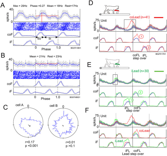
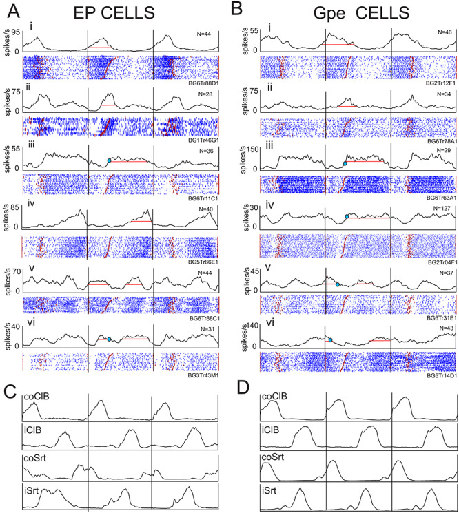
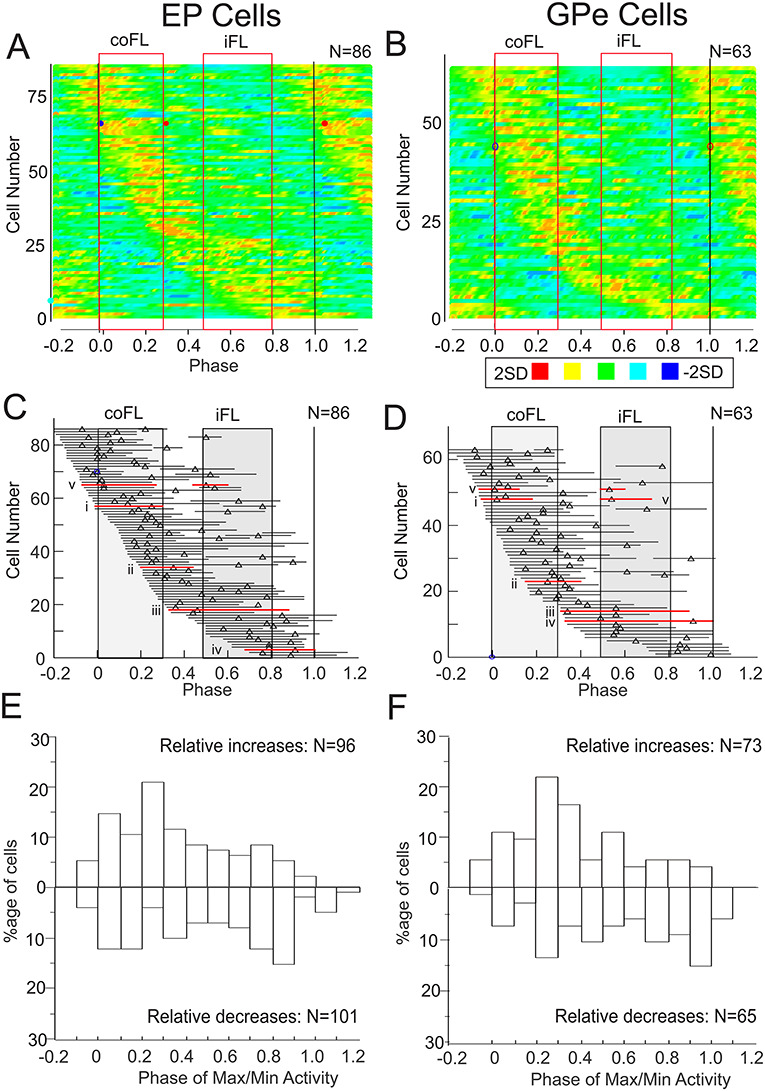
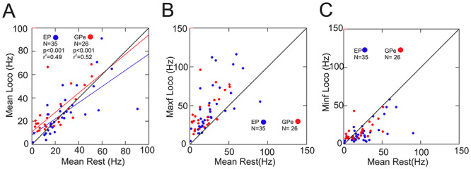
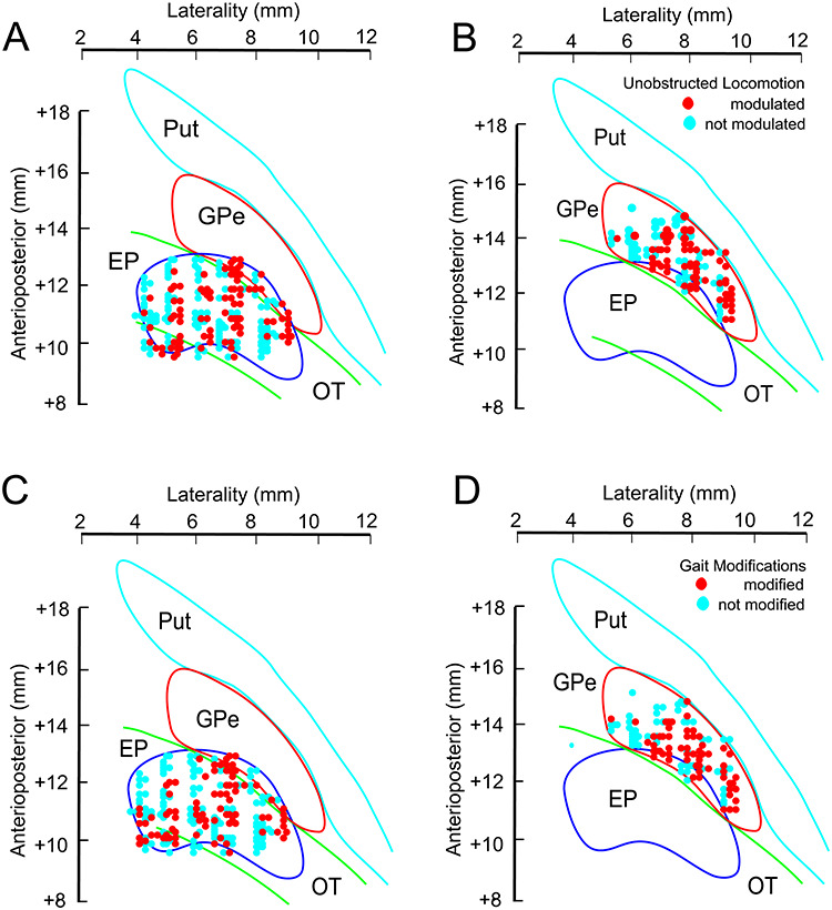
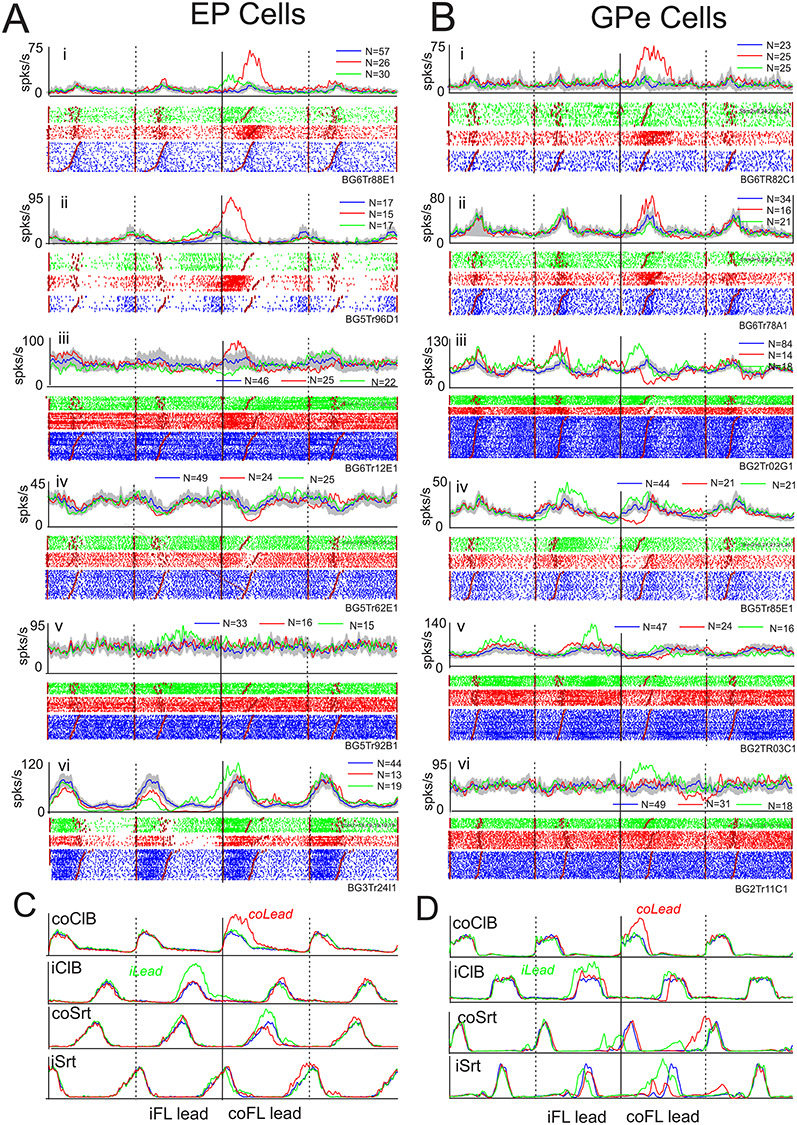
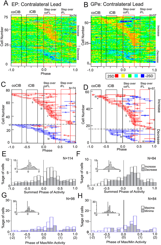
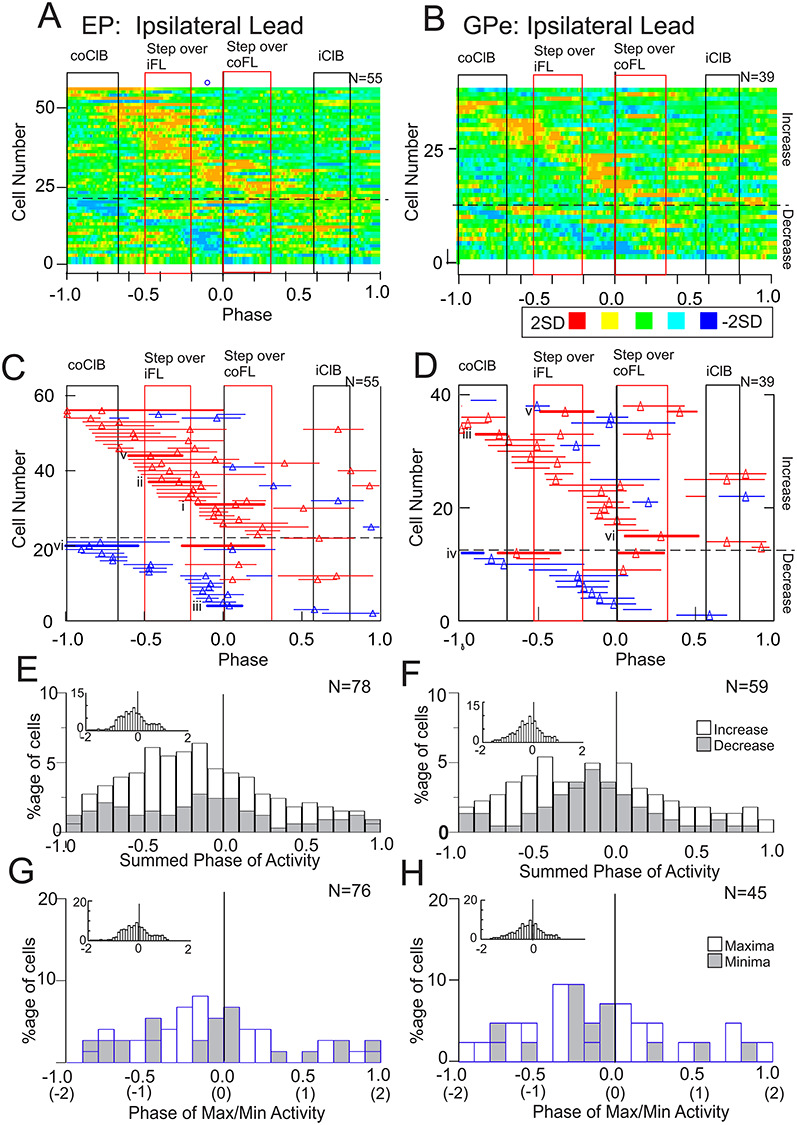
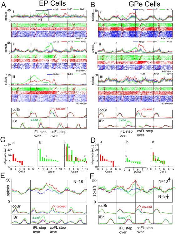
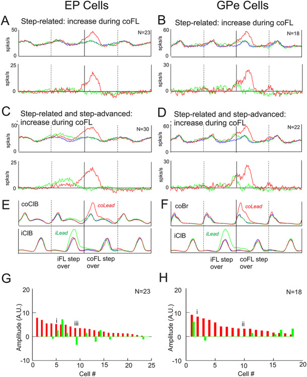
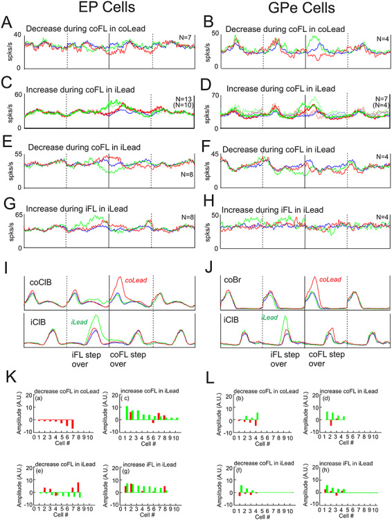
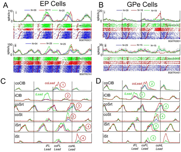
We tested the hypothesis that the entopeduncular (EP) nucleus (feline equivalent of the primate GPi) and the globus pallidus (GPe) contribute to both the planning and execution of locomotion and voluntary gait modifications in the cat. We recorded from 414 cells distributed throughout these two nuclei (referred to together as the pallidum) while cats walked on a treadmill and stepped over an obstacle that advanced towards them. Neuronal activity in many cells in both structures was modulated on a step-by-step basis during unobstructed locomotion and was modified in the step over the obstacle. On a population basis, the most frequently observed change, in both the EP and the GPe, was an increase in activity prior to and/or during the swing phase of the step over the obstacle by the contralateral forelimb, when it was the first limb to pass over the obstacle. Our results support a contribution of the pallidum, in concert with cortical structures, to the control of both the planning and the execution of the gait modifications. We discuss the results in the context of current models of pallidal action on thalamic activity, including the possibility that cells in the EP with increased activity may sculpt thalamo-cortical activity.

Keywords: basal ganglia; entopeduncular nucleus; globus pallidus; pallidum; visually guided gait modification.


Figures

Figure 1
Figure 1
Quantification of cell activity. A, B, example of a modulated (A) and unmodulated (B) cell. For each cell we show a perievent histogram (PEH) of the averaged activity of the cell during unobstructed locomotion, together with a raster display of cell activity and the averaged activity of the contralateral and ipsilateral forelimb flexors (coF, iF). The activity during the cycle is repeated 3 times to emphasize the nature of the rhythmical activity. Data are synchronized to the onset of activity in the coF. The horizontal red line indicates the mean activity during the step cycle (mean), and the red vertical line indicates the maximum discharge frequency (max) and the phase of that activity (phase). Sw and St in A indicate the swing and stance phases, respectively, of the step cycle. Rest indicates the resting rate discharge frequency measured just before locomotion. C: the cell discharge is displayed in a circular format with the onset of the step cycle beginning at 0 and moving clockwise. The arrow gives an indication of the dispersion of the discharge (r) with the maximum value for a cell discharging always in the same place being 1. The value of p indicates the probability that the discharge is directional. D, E: Averaged unit and EMG activity from a different cell when the contralateral (D) or the ipsilateral (E) limb is the first to step over the obstacle. F: contralateral and ipsilateral lead superimposed. Activity in DF is synchronized to the onset of activity in the coF. Blue traces indicate activity during unobstructed locomotion and the shaded gray area indicates the interval of confidence (P = 0.01) of the standard error (SE) of the mean. Red traces indicate activity when the contralateral limb is the first to step over the obstacle and green traces the activity when the ipsilateral limb leads. coFL and iFL beneath the displays in D, E indicate when the contralateral and ipsilateral limb, respectively passed over the obstacle. “Lead step over” in F indicates when the lead limb passed over the obstacle in the contralateral and ipsilateral lead condition. Rectangles on the cell trace in D, E indicate cell activity during the gait modification that is considered to be significantly different from that in unobstructed locomotion. Numbers within circles on D, E indicate the sequence of activation of the coF and iF.
Figure 2
Figure 2
Examples of discharge activity during unobstructed locomotion. A, B: 6 examples (i–vi) of cells recorded from the EP (A) and the GPe (B). For each cell, we illustrate perievent histograms (PEHs) and raster displays triggered on the onset of activity of the contralateral Br/ClB. In each case the central step cycle represents the cycle 2 (TM2) or 3 (TM1) steps before the step over the obstacle, together with the preceding and the following cycle. The black vertical lines delimit the three step cycles. The horizontal red line(s) through the PEH in the central cycle indicates the mean level of activity (see Methods). Cell activity in this and all other figures is rank-ordered according to the duration of the period of ClB/Br activity (red staggered lines in the raster displays). Small blue circles, when present, indicate the discharge frequency of the cell in the absence of locomotion (resting rate: data were not available for all cells). C, D: averaged EMG activity from the coClB and iClB, together with that from the contralateral and ipsilateral sartorius muscles (coSrt and iSrt, hindlimb flexor muscles), recorded simultaneously with the cell illustrated in Aiii for part C and simultaneously with the cell illustrated in Biv for part D.
Figure 3
Figure 3
Population activity during unobstructed locomotion. A, B: heat maps compiled from all significantly modulated cells in the EP and GPe for which we could also visually determine clear periods of activity (see Methods). Cell activity is rank-ordered according to the phase of the onset of the period of increased activity (starting at −0.2), as determined from PEHs of the type illustrated in Figure 2. Each horizontal line represents periods of modified activity in one cell and the discharge activity of each cell has been transformed into a Z score (the standard deviation of the discharge in each bin with respect to the mean). Each cell is scaled to maximum and minimum values of ±2.0SD. In bins in which the values exceeded formula image values were manually set to 2. Positive and negative Z scores are divided into 3 equal divisions represented by the colors in the key below Figure 3B, with red indicating maximum peak activity. C, D: phase plots indicating the period(s) of discharge activity exceeding the mean activity of the cell (see Methods and Fig. 2). Cells are rank-ordered as in parts A, B and triangles indicate the phase of the peak activity, when detectable. Red horizontal lines indicate the phase plots for cells i–v illustrated in Figure 2A and B. Red, vertically-oriented, rectangles in AD indicate the averaged activity of the coClB and the iClB as measured from 22 cells included in the plots. E, F: Histograms showing the distribution of the phase of the maximum (for relative increases) and minimum (for relative decreases) discharge for the 86 cells in A and the 63 cells in B. Note that some cells had more than one peak during the step cycle (see C, D) so that the number of values in the histograms of E, F is greater than the number of cells. Further, maxima and minima were not valid for all cells (plateaus for example) so that the number of maxima and minima is not the same. Binwidth = 10% of the step cycle (phase difference of 0.1). Data in AF are synchronized with respect to the onset of the coClB/Br (phase = 0.0).
Figure 4
Figure 4
Discharge activity at rest. A: Scatterplots of the mean discharge frequency during unobstructed locomotion (as calculated in Fig. 1) as a function of the mean discharge frequency at rest (during either quiet sitting/lying or standing: data combined). B, C: plots of the maximum (B) and minimum (C) discharge frequency during locomotion as a function of the discharge at rest. Blue symbols = EP; red symbols = GPe. Blue and red lines in A indicate the linear regressions for the EP and GPe. Black diagonal line in AC indicates the line of equivalence.
Figure 5
Figure 5
Localization of the recordings. A, B: recording sites of all cells included in our database from the EP (A, 267 cells) and the GPe (B, 147 cells) plotted on standardized representations of each nucleus in the horizontal plane (see Methods). Nuclei are positioned within the stereotaxic framework of the atlas of Berman (Berman and Jones 1982). Cells recorded in the same penetration have been slightly displaced (jittered by a maximum of 0.2 mm) one from the other to represent the number of cells recorded, rather than simply the number of tracks. The plots differentiate cells that were significantly modulated during locomotion (red circles) from those that showed no modulation (blue circles). The position of the putamen (Put) and the optic tract (OT) are also indicated. C, D. the location of those cells whose activity was modified during the gait modification (red circles).
Figure 6
Figure 6
Examples of cell discharge during gait modifications. We illustrate six examples of cell discharge (i–vi) recorded from the EP (A) and the GPe (B) during the voluntary gait modifications. For each cell, we illustrate both PEHs and rasters showing cell activity in control steps (blue traces); during steps over the obstacle in which the contralateral forelimb was the first to step over the obstacle (red traces) and trials in which the ipsilateral limb was the first to step over the obstacle (green traces). Shaded region around the control trials indicates the 0.01 interval of confidence of the standard error of the mean. Note that contralateral and ipsilateral lead trials were intermingled randomly with the control steps during the recording session. All data are synchronized to the onset of activity of the coClB/Br in the step over the obstacle by the contralateral forelimb (solid vertical lines). We display 2 step cycles before this step and 1 step cycle after (step cycles delimited by vertical lines). Note that because we always synchronize on the coClB, the step over the obstacle by the ipsilateral forelimb occurs following coClB in the contralateral lead condition but precedes it in the ipsilateral lead condition (see Fig. 1). C, D: averaged EMG activity. N, indicates number of trials for each condition.
Figure 7
Figure 7
Population activity during the contralateral lead condition. A-B: Heat maps of the change in activity when the cat first steps over the obstacle with the contralateral limb. Data are initially treated by subtracting the control activity (blue traces in Fig. 6) from the discharge activity during the contralateral lead condition (red traces in Fig. 6). Subsequently, we calculate the Z-score and plot the data as in Figure 3. Data are organized so that we plot first all cells in which the initial significant change in activity was an increase (above the horizontal dotted line in A, B) and then subsequently those cells in which the initial change was a decrease (below the line). C, D: Phase plots indicating the periods of significantly modified activity (see Methods). Red horizontal lines indicate periods of significantly increased activity and blue lines indicate periods with a significant decrease. Thicker red or blue lines with associated Roman numerals indicate cells illustrated in Figure 6. Vertical rectangles in A-D indicate the periods of activity of the coClB and iClB in the step before and the step over the obstacle, with the red rectangles indicating the period of activity of the ClB during the step over the obstacle by the contralateral forelimb and ipsilateral forelimb. E, F: Summed changes in activity for the same period (−1.0 to 1.0) as illustrated in AD. The histogram effectively sums the periods of activity illustrated in C, D in bins equal to 0.1 of the step cycle. Data are shown separately for cells with increased (open bars) and decreased (shaded bars) activity but are shown as a percentage of the total summed activity (increases and decreases combined). G, H: Phase of maxima (increased activity) and minima (decreased activity) of the changes in activity. Note that peaks were not identifiable for all periods of significantly modified activity. AH indicate activity for 1 step cycle (2steps) before and after the onset of activity in the coClB (phase = 0, solid, black vertical line). Note that on the x-axis for G, H, we also indicate the number of steps before and after the step over the obstacle (in parentheses). Insets in EH indicate data for all cells (increases and decreases combined) and extended to 2 step cycles before and after the step over the obstacle. N in AD indicates the number of cells. N in EF indicates the number of periods of significantly modified activity while N in G, H indicates the number of periods of modified activity for which the phase of peak activity could be defined.
Figure 8
Figure 8
Population activity during the ipsilateral lead condition. AH: Data are organized as in Figure 7, with the solid black vertical line in AH at time = 0.0 indicating the onset of the period of activity in the coClB associated with the step over the obstacle by the contralateral forelimb. However, in this condition, the step over the obstacle by the ipsilateral limb precedes this step (see Fig. 1). As in Figure 7, the period of activity of the coClB and the iClB during the step over the obstacle, and in the preceding step cycle, is indicated by the rectangles and bars. Thicker red bars and Roman numerals indicate the activity during the ipsilateral lead condition of the cells illustrated in Figure 6.
Figure 9
Figure 9
Step-advanced activity. A, B: Examples of step-advanced cells (i-iii) in the EP and GPe. Data are organized as for Figure 6. EMG activity in A was recorded simultaneously with cell Aiii, EMG activity in B was recorded simultaneously with Bi. C, D: magnitude of the change in activity for cells showing step-advanced activity only in the contralateral lead condition (a), only in the ipsilateral lead condition (b), or in both conditions (c). Values indicate the total integrated value of the averaged activity during the burst minus the control activity in the same period (see box in Fig. 9Ai [INT)]). Units are arbitrary but are comparable for each cell. Data are rank-ordered (left to right) according to the magnitude of the burst; in Figure 9Cc and Dc, the values in the contralateral lead condition are used to rank-order the data. Roman numerals indicate the cells illustrated in Figure 9A and B. E, F: population averages of the EP and GPe cells compiled from all cells that showed an increase in activity prior to the step over the obstacle, regardless of condition. In F we additionally display the average of those cells that showed a decrease in activity prior to the step over the obstacle in the ipsilateral lead condition.
Figure 10
Figure 10
Example step-related population activity averages. A, B. population averages of step-related cells in the EP (A) and the GPe (B) that showed activity changes beginning just before (<0.2 step cycles) or during the step over the obstacle, regardless of any other changes in activity. Data are displayed superimposed on the control activity in the top row and after subtraction of the control activity (before averaging) in the bottom row. C, D: similar plots, but now including selected step-advanced cells (see text). E, F: averaged EMG activity taken from the averages of A, B. The color of the traces follows the conventions of Figure 6. N indicates the number of cells included in the averages. G, H: magnitude of the changes in activity of the step-related cells. The roman numerals identify cells illustrated in Figure 6. The magnitude of the responses is scaled identically to those of the step-advanced cells of Figure 9.
Figure 11
Figure 11
Additional step-related population averages. AH: population averages created from cells that showed different patterns of activity. Convention as in Figure 10. I, J: Averaged EMG activity taken from the averages in A, B. K, L: magnitude of the responses of the changes in activity of the individual cells included in the population averages of AH (indicated by a-h). Magnitudes are rank-ordered according to locomotor condition and are comparable with those in Figures 9 and 10.
Figure 12
Figure 12
Cells discharging in relation to the hindlimb. A, B: Examples of cells in the EP (A) and the GPe (B) showing their major change in activity during the step over the obstacle by the contralateral hindlimb. Data organized as in Figure 6, with data aligned on the onset of activity in the coClB/Br. Numbers within circles indicate the sequence of activation of the contralateral fore- and hindlimb muscles in the contralateral (illustrated in C) and ipsilateral (illustrated in D) lead conditions. Eding step.

References

    1. Alexander GE, Delong MR, Strick PL. 1986. Parallel organization of functionally segregated circuits linking basal ganglia and cortex. Annu Rev Neurosci. 9:357–381. - PubMed
    1. Allen GI, Tsukuhara N. 1974. Cerebrocerebellar communication systems. Physiol Rev. 54:957–1006. - PubMed
    1. Amos A, Armstrong DM, Marple-Horvat DE. 1990. Changes in the discharge patterns of motor cortical neurones associated with volitional changes in stepping in the cat. Neurosci Lett. 109:107–112. - PubMed
    1. Anderson ME, Horak FB. 1985. Influence of the globus pallidus on arm movements in monkeys. III. Timing of movement-related information. J Neurophysiol. 54:433–448. - PubMed
    1. Anderson ME, Turner RS. 1991. A quantitative analysis of pallidal discharge during targeted reaching movement in the monkey. Exp Brain Res. 86:623–632. - PubMed

Publication types