. 2020 Jun;15(6):1992-2023.
doi: 10.1038/s41596-020-0318-4. Epub 2020 May 13.

Assembly and operation of an open-source, computer numerical controlled (CNC) robot for performing cranial microsurgical procedures

Affiliations

Assembly and operation of an open-source, computer numerical controlled (CNC) robot for performing cranial microsurgical procedures

Mathew L Rynes et al. Nat Protoc. 2020 Jun.

Abstract

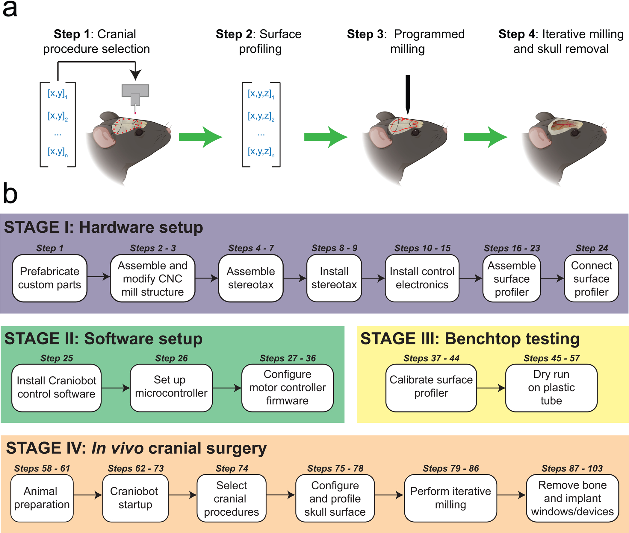
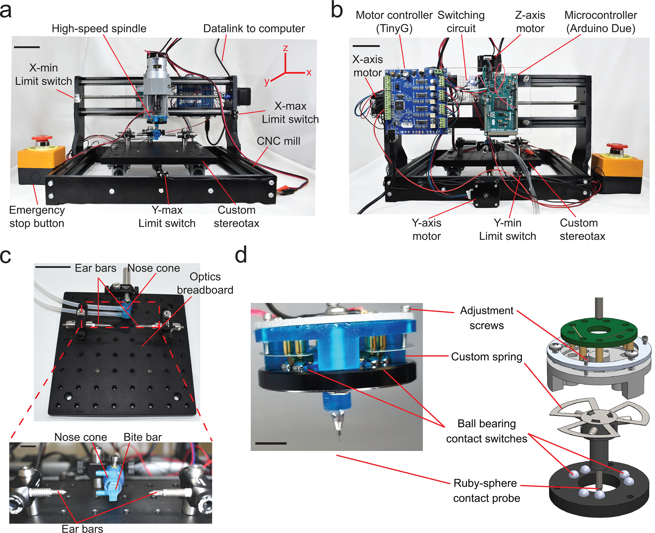
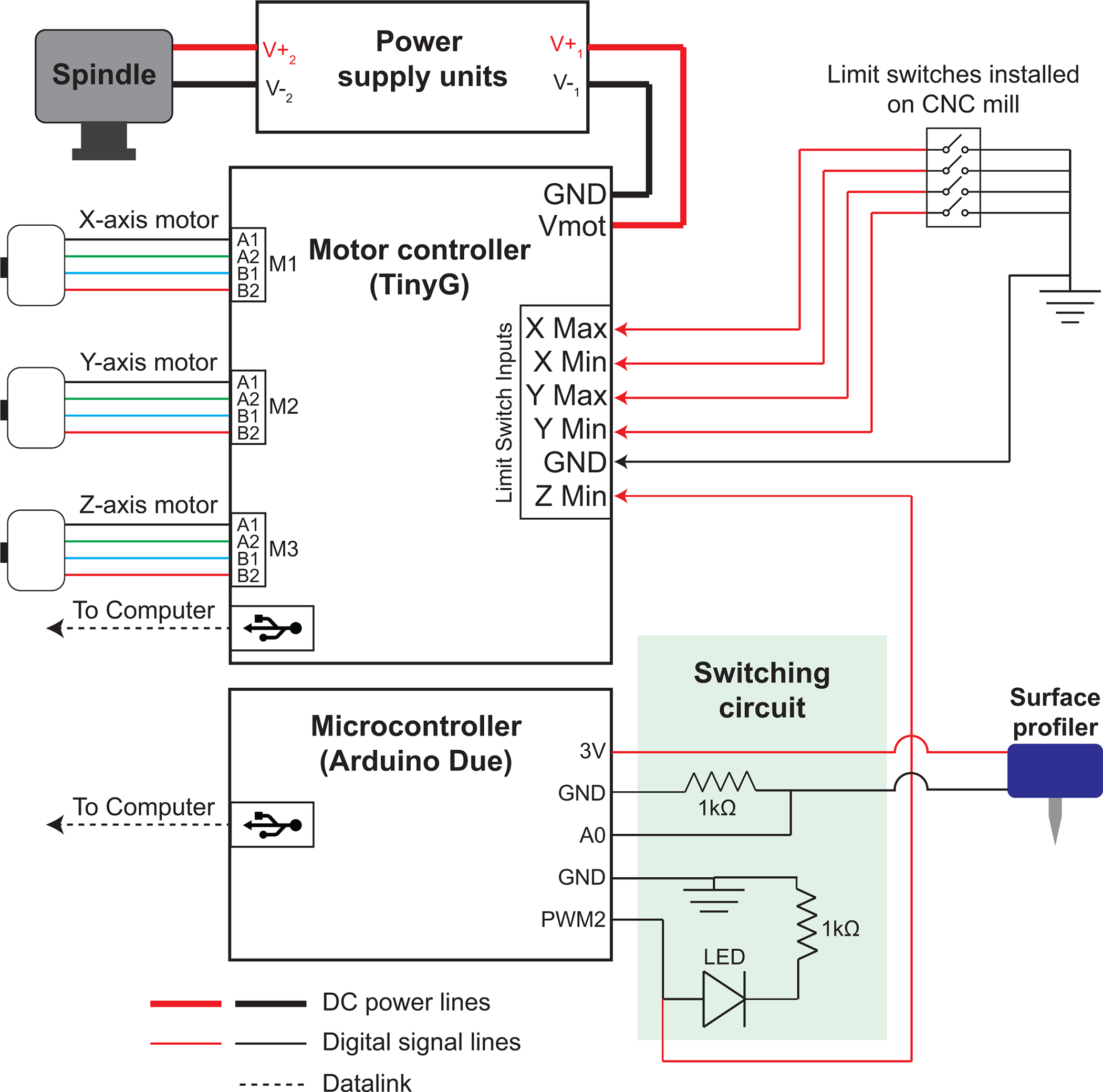
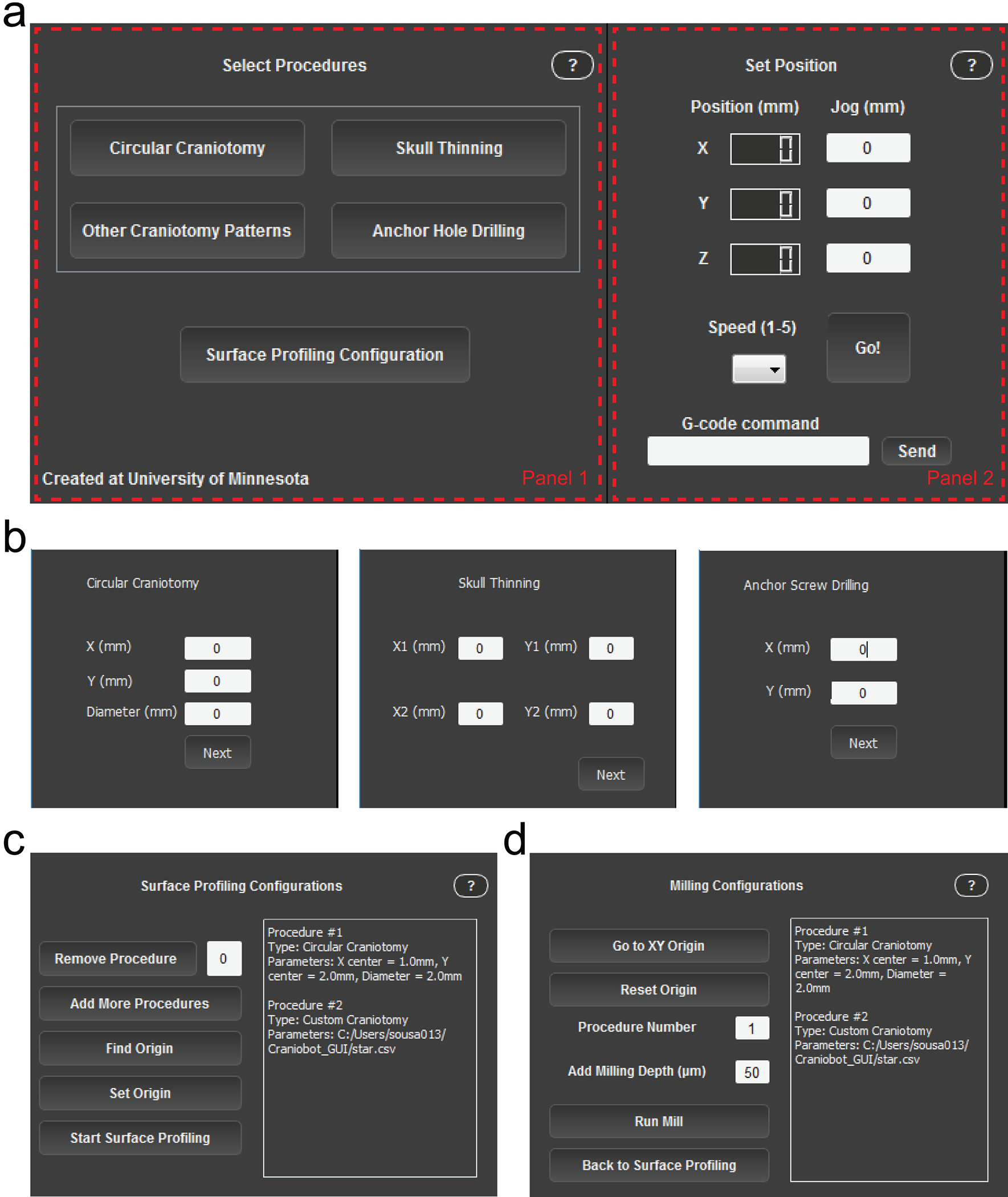
Cranial microsurgery is an essential procedure for accessing the brain through the skull that can be used to introduce neural probes that measure and manipulate neural activity. Neuroscientists have typically used tools such as high-speed drills adapted from dentistry to perform these procedures. As the number of technologies available for neuroscientists has increased, the corresponding cranial microsurgery procedures to deploy them have become more complex. Using a robotic tool that automatically performs these procedures could standardize cranial microsurgeries across neuroscience laboratories and democratize the more challenging procedures. We have recently engineered a robotic surgery platform that utilizes principles of computer numerical control (CNC) machining to perform a wide variety of automated cranial procedures. Here, we describe how to adapt, configure and use an inexpensive desktop CNC mill equipped with a custom-built surface profiler for performing CNC-guided microsurgery on mice. Detailed instructions are provided to utilize this 'Craniobot' for performing circular craniotomies for coverslip implantation, large craniotomies for implanting transparent polymer skulls for cortex-wide imaging access and skull thinning for intact skull imaging. The Craniobot can be set up in <2 weeks using parts that cost <$1,500, and we anticipate that the Craniobot could be easily adapted for use in other small animals.


Conflict of interest statement

COMPETING INTERESTS

The authors declare no competing interests.

Figures

Figure 1.
Figure 1.. Overview: (a) Steps of the automated cranial surgery using the Craniobot:
Step 1: A set of n xy-coordinate of pilot points defining a selected cranial procedure is used to create a 2D path on the mouse skull. Step 2: A surface profiler is used to register the z-coordinate at each of those points, creating a set of n 3D points that can be interpolated to generate a continuous path mapped onto the skull surface. Step 3: A z-offset is applied to the measured path to generate skull milling commands. Step 4: Computer numerical controlled (CNC) milling is performed with the depth of milling increased iteratively until the desired depth is achieved for a given cranial procedure. (b) A summary of the protocol for adapting a desktop CNC milling machine for automated cranial microsurgeries in mice is given.
Figure 2.
Figure 2.. Craniobot hardware:
(a) Front view of the Craniobot which consists of a three-axis CNC mill, a custom built stereotax, and a high-speed spindle. Scale bar, 5 cm. (b) Back view of the Craniobot showing three stepper motors and control electronics including a motor controller, a microcontroller, and a switching circuit. Scale bar, 5 cm. (c) Photographs of the custom built stereotax. Detailed step-by-step instructions on assembling the CNC mill and adapting it for automated surgeries is shown in Supplementary Figure 1. Scale bars in c and bottom inset, 5 cm and 1 cm, respectively. (d) Photograph and computer-aided design (CAD) schematic of the custom-built surface profiler indicating the key parts. Scale bar, 10 mm. Detailed step-by-step instructions on assembling the surface profiler is shown in Supplementary Figure 2.
Figure 3.
Figure 3.. Craniobot control electronics:
DC power supplies provide power to the CNC mill and the high-speed spindle. An open-source motor controller is used to drive the stepper motors in the x, y, and z directions. It connects to the computer via universal serial bus (USB) interface. Four limit switches, two each for the x and y axes to ensure the motors do not exceed the maximum travel range, are connected to the limit switch input terminals in the motor controller. One of the limit switch circuits in the z-direction is connected to an emergency stop button, and the other limit switch circuit is connected to the surface profiler via a switching circuit. A microcontroller is used to connect the surface profiler to the motor controller via the switching circuit.
Figure 4.
Figure 4.. Craniobot software graphic user interface (GUI):
(a) Screenshot of the GUI during ‘Select Procedures’ mode. Panel 1 changes as the Craniobot progresses through the different stages of the program. Panel 2 is fixed, allowing the user to track spindle position, jog the CNC machine and send custom G-code commands (b) Panel 1 when selecting the parameters that define a circular craniotomy (left), skull thinning procedure (middle), and anchor hole drilling (right). (c) Panel 1 during surface profiling. (d) Panel 1 during iterative milling. Table 2 provides a list of user interface elements in the GUI and describes their functions.
Figure 5.
Figure 5.. Surface profiler performance
(a) Calibration curve indicating the change in actuation force required to trigger the surface profiler as a function of nominal turns of the adjustment screws. The green bar indicates the range of actuation forces in which the surface profiler can be used for profiling the skull surface. (b) Average point cloud computed after profiling 192 points across the dorsal cortex of a C57BL/6J mouse skull superimposed on a micro-CT scan of the same subject. Scale bar, 1 mm. The red dot indicates Bregma. (c) Standard deviations of repeated measurements taken across the same points in (b) showing the spatial variation in measurement error. The red dot indicates Bregma. (d) Histogram of measurement errors at 192 points each in six mice. Figure 5 adapted from ref: Ghanbari*, Rynes* et al Sci Rep 2019. All experiments were approved by the University of Minnesota’s Institutional Animal Care and Use Committee (IACUC).
Figure 6:
Figure 6:. Benchtop testing of Craniobot function on plastic tube and key steps during surface profiling:
(a) Photograph illustrating a plastic tube adapted and secured in the Craniobot stereotax for mock circular craniotomy procedure. Scale bar, 10 mm. (b) Top left: Photograph illustrating the surface profiler stylus tip at the marked ‘origin’ on the surface of the plastic tube. Top right: Photograph illustrating the end mill at the marked ‘origin’ on the surface of the plastic tube. Bottom: Photograph of end result of milling a circular trench of depth 50 μm using the Craniobot. Scale bars, 1 mm. Surface profiling: (c) Left: Photograph of the stylus prior to starting ‘Find Origin’. Middle: Stylus after stopping at Bregma. Right: Photograph of the end mill positioned at Bregma prior to CNC milling. Scale bars, 1 mm. (d) Left: Result of surface profile displayed after profiling a circular craniotomy of diameter 3 mm centered at 2 mm to the right and 2 mm posterior to Bregma. Center: Result of surface profile displayed after profiling a large craniotomy covering both hemispheres of the dorsal cortex. Right: Result of surface profiles displayed after profiling a rectangular area with non-adjacent corners located at (−1.5 mm ML, −1.5 mm AP) and (−3.5 mm ML, −3.5 mm AP) for skull thinning. Circular craniotomy and whole dorsal cortex craniotomy surface profiles were performed on a male, 12-week-old C57BL/6J mouse. Profiling for skull thinning procedure was performed on a male, 16-week-old C57BL/6J mouse. Orange dots indicate pilot points at which the skulls were profiled, blue dots indicate points offset by a depth of 50 μm. Orange lines simulate interpolated path taken by the end mill at the skull surface. Blue lines simulate the linearly interpolated path taken by the end mill if offset by a depth of 50 μm. (e) Erroneous surface profiles resulting from false positive measurements: Left: when profiling for a circular craniotomy and Right: when profiling for a craniotomy over the dorsal cortex. False positive measurements are indicated by red circles.
Figure 7.
Figure 7.. Surface-profile-guided machining:
(a) Boxplot of the measured trench depth for four possible combinations of surface profiling and end mills for 50 μm depth of cut. Inset: Photomicrographs of trenches milled in the anterior posterior direction by the Craniobot. Scale bar, 250 μm (b) Bar plots of the final depth of milling used for performing craniotomies over the whole dorsal cortex in three strains of mice of ages ranging from 8 to 20 weeks. (c) Micro-CT scan of a mouse skull after 50 μm deep trench milled for a craniotomy across the whole dorsal cortex. Scale bar, 1 mm. (d) Micro-CT scan of a mouse skull after surface milling down to a depth of 70 μm for a skull thinning procedure. Scale bar, 1 mm. (a), (c), and (d) are adapted from ref: Ghanbari*, Rynes* et al Sci Rep 2019. All experiments were approved by the University of Minnesota’s Institutional Animal Care and Use Committee (IACUC).
Figure 8.
Figure 8.. Chronic implantation using the Craniobot:
(a) Photograph taken from a Thy1-GCaMP6f mouse with a chronically implanted circular glass coverslip. Scale bar, 1 mm. (b) Photograph of a Thy1-GCaMP6f mouse taken with a chronically implanted See-Shell. Scale bar, 2 mm. (c) Photograph taken from an adult male C57BL/6J mouse skull after a thinning operation using the Craniobot reinforced with clear dental cement and a glass coverslip. Surface milling was performed to a depth of 70 μm in a 2 mm × 2 mm square. Scale bar, 1 mm. (d) Representative images of stained microglia via Iba1 (Wako Cat# 019–19741, RRID:AB_839504) staining and DAPI shown in both mice that underwent automated surface milling and non-surgical control mice. Images were taken at 20X magnification (top row) and 40X magnification (bottom row). Scale bars, 100 μm (top row) and 25 μm (bottom row). (e) Bar graph of average count of microglia in 891 × 662 μm of cortical tissue directly underneath the bone tissue milled using the Craniobot compared with microglia count from same brain region in non-surgerized mice. n. s indicates not significant (n= 6 mice in each group, p = 0.08, Student’s t-test). (f) Bar graph of average soma size of microglia in cortical tissue directly underneath the bone tissue milled using the Craniobot compared with average soma size of microglia from same brain region in non-surgerized mice. n. s indicates not significant (n = 10 cells assessed in each group, p = 0.61, Student’s t-test) (a), (c), (d – top row), and (e) are adapted from ref: Ghanbari et al Sci Rep 2018. All experiments were approved by the University of Minnesota’s Institutional Animal Care and Use Committee (IACUC).

References

    1. Jun JJ et al. Fully integrated silicon probes for high-density recording of neural activity. Nature 551, 232 (2017). - PMC - PubMed
    1. Shobe JL, Claar LD, Parhami S, Bakhurin KI & Masmanidis SC Brain activity mapping at multiple scales with silicon microprobes containing 1,024 electrodes. J. Neurophysiol. (2015). doi:10.1152/jn.00464.2015 - DOI - PMC - PubMed
    1. Scholvin J et al. Close-Packed Silicon Microelectrodes for Scalable Spatially Oversampled Neural Recording. Biomed. Eng. IEEE Trans. 63, 120–130 (2016). - PMC - PubMed
    1. Berényi A et al. Large-scale, high-density (up to 512 channels) recording of local circuits in behaving animals. J. Neurophysiol. (2014). doi:10.1152/jn.00785.2013 - DOI - PMC - PubMed
    1. Voigts J, Siegle J, Pritchett DL & Moore CI The flexDrive: An ultra-light implant for optical control and highly parallel chronic recording of neuronal ensembles in freely moving mice. Front. Syst. Neurosci. (2013). doi:10.3389/fnsys.2013.00008 - DOI - PMC - PubMed

Publication types