. 2020 May 21;10(1):8455.
doi: 10.1038/s41598-020-64669-y.

Collapse dynamics of spherical cavities in a solid under shock loading

Affiliations

Collapse dynamics of spherical cavities in a solid under shock loading

E M Escauriza et al. Sci Rep. .

Abstract

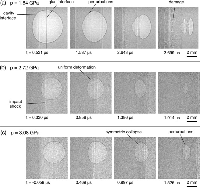
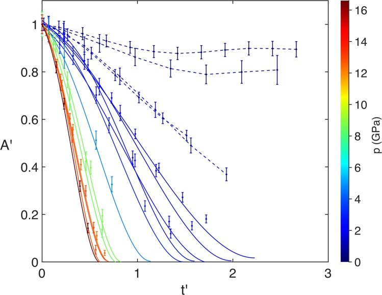
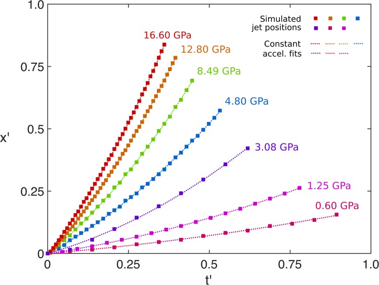
Extraordinary states of highly localised pressure and temperature can be generated upon the collapse of impulsively driven cavities. Direct observation of this phenomenon in solids has proved challenging, but recent advances in high-speed synchrotron radiography now permit the study of highly transient, subsurface events in real time. We present a study on the shock-induced collapse of spherical cavities in a solid polymethyl methacrylate medium, driven to shock states between 0.49 and 16.60 GPa. Utilising multi-MHz phase contrast radiography, extended sequences of the collapse process have been captured, revealing new details of interface motion, material failure and jet instability formation. Results reveal a rich array of collapse characteristics dominated by strength effects at low shock pressures and leading to a hydrodynamic response at the highest loading conditions.


Conflict of interest statement

The authors declare no competing interests.

Figures

Figure 1
Figure 1
Schematic diagrams showing the setup for the experiments. In (a), for the single-stage experiments, the projectile is accelerated toward the target under the action of a single high-pressure reservoir. (b) An enlarged view of the flyer plate and target, which have cylindrical symmetry about the axis of impact. (c) For the two-stage experiments, high-pressure gas accelerates a piston towards a transition section, compressing and heating the helium gas ahead of it. This gas subsequently bursts a diaphragm, launching a sabot toward the target mounted at the end of the muzzle. Both gun systems are oriented normal to the X-ray beam to capture the transverse profile of the shock wave and cavity.
Figure 2
Figure 2
Illustration showing key features of the experiment. (a) Schematic diagram showing the imaging system, which is placed 7 m away from the target chamber. The X-ray pulses are absorbed by a LYSO:Ce scintillator after passing through the experiment, which re-emits visible photons. The front- and rear-surface scintillator emissions are folded away from the X-ray beam path by a mirror and pellicle beamsplitter, respectively, and are captured by two UHS cameras. (b) Model of the photon flux (ph/mm2/0.1%bw/s) with respect to photon energy (keV) of ESRF beamline ID19, calculated in XOP. (c) Radiographs of a PMMA target containing a spherical cavity. The left image shows the stationary cavity before impact. The right image shows the target after impact, with the velocities and densities given.
Figure 3
Figure 3
Radiograph sequences showing shock-cavity interactions in the strength-dominated regime. (a) A 4 mm cavity and 0.49 GPa shock. (b) A 6 mm cavity and 0.59 GPa shock. (c) A 6 mm cavity and 1.25 GPa shock.
Figure 4
Figure 4
Radiograph sequences showing shock-cavity interactions in the transition regime. (a) A 6 mm cavity and 1.84 GPa shock. (b) A 4 mm cavity and 2.72 GPa shock. (c) A 4 mm cavity and 3.08 GPa shock.
Figure 5
Figure 5
Radiograph sequences showing shock-cavity interactions in the hydrodynamic regime. (a) A 4 mm cavity and 8.63 GPa shock. (b) A 6 mm cavity and 12.80 GPa shock. (c) A 6 mm cavity and 16.60 GPa shock, with insets showing the rear-surface optical images of the toroidal plasma emission.
Figure 6
Figure 6
Plots of A′ vs. t′. The colour bar shows the shock pressure p. In the low-pressure region the dashed lines show the trajectory of the projected area, with a piecewise linear interpolation between each point. In the higher-pressure region the solid lines show the fitting of each curve with Eq. 4.
Figure 7
Figure 7
Logarithmic plot of tcol vs. p/p0 for shock-induced and Rayleigh collapse. The open circles show the collapse times obtained from curve fitting and the closed symbols show the collapse times estimated from the radiographs. The solid black line shows the fit for the data, with p > 1.25 GPa, tcol=617(p/p0)0.58, and the solid red line shows the fit from the Swantek & Austin study, tcol,SA=305(p/p0)0.55. The dashed black and red lines show the respective theoretical Rayleigh curves for PMMA, tcol,PMMAR=137(p/p0)0.5, and water, tcol,gelR=69(p/p0)0.5.
Figure 8
Figure 8
Plots of x′ vs. t′ extracted from simulations in Hytrac, with constant-acceleration quadratic fits.
Figure 9
Figure 9
Plots of x′ vs. t′. The solid lines show a quadratic fit for each interaction and a linear change in the initial shock pressure p is represented by the colour bar. The dashed lines show a piecewise linear interpolation of the low-pressure data.
Figure 10
Figure 10
Plots of a′ vs. p, with the data for the experiments with shock pressures of 4.80 GPa and above. The solid line shows the linear fit of the experimental data and the dashed line shows the quadratic fit for the simulations.

References

    1. Rayleigh, L. VIII. On the pressure developed in a liquid during the collapse of a spherical cavity. Philosophical Magazine34, 94–98. issn: 1941–5982 (1917).
    1. Kornfeld M, Suvorov L. On the Destructive Action of Cavitation. Journal of Applied Physics. 1944;15:495. doi: 10.1063/1.1707461. - DOI
    1. Naudé C, Ellis AT. On the Mechanism of Cavitation Damage by Nonhemispherical Cavities Collapsing in Contact With a Solid Boundary. Journal of Basic Engineering. 1961;1:1–9.
    1. Field, J. E. The physics of liquid impact, shock wave interactions with cavities, and the implications to shock wave lithotripsy. Physics in Medicine and Biology36, 1475–1484. issn: 0031–9155 (1991). - PubMed
    1. Kodama T, Takayama K. Dynamic Behaviour of Bubbles During Extracorporeal Shock-Wave Lithotripsy. Ultrasound in Medicine & Biology. 1998;24:723–738. doi: 10.1016/S0301-5629(98)00022-2. - DOI - PubMed