. 2020 May 23;21(1):323.
doi: 10.1186/s12891-020-03300-7.

Tibiofemoral rotation alignment in the normal knee joints among Chinese adults: a CT analysis

Affiliations

Tibiofemoral rotation alignment in the normal knee joints among Chinese adults: a CT analysis

Yufeng Lu et al. BMC Musculoskelet Disord. .

Abstract

Background: Consensus on tibial rotation in total knee arthroplasty (TKA) remains controversial. The present study aimed to investigate the closest anatomical reference to surgical epicondylar axis (SEA) among 10 tibial markers in Chinese adults.

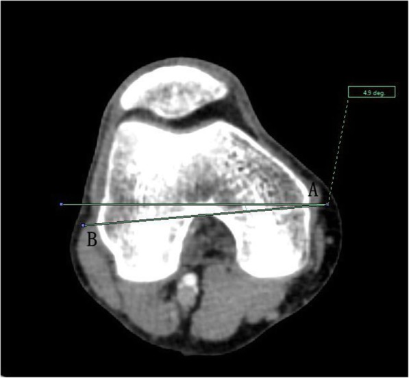
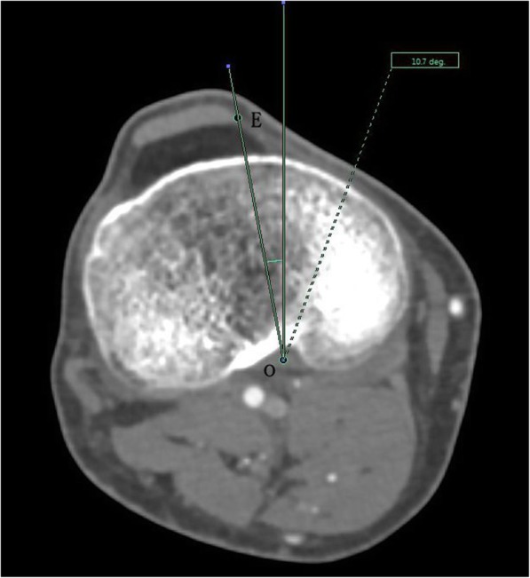
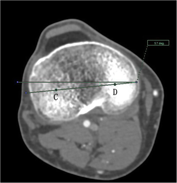
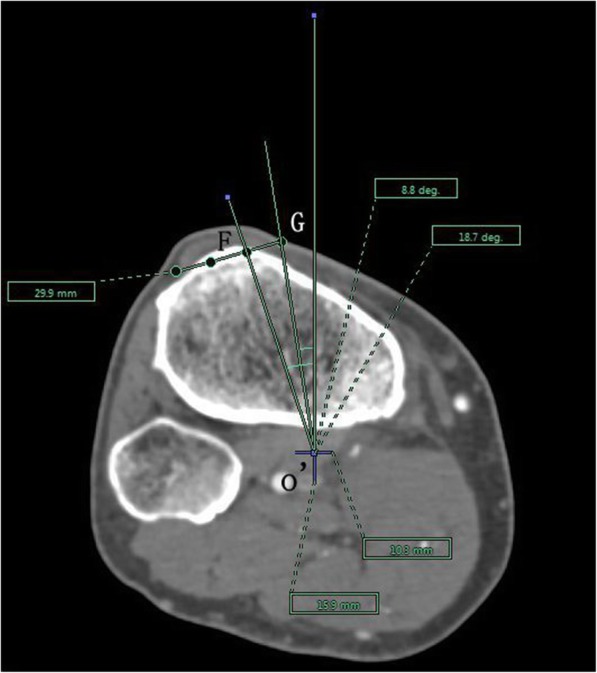
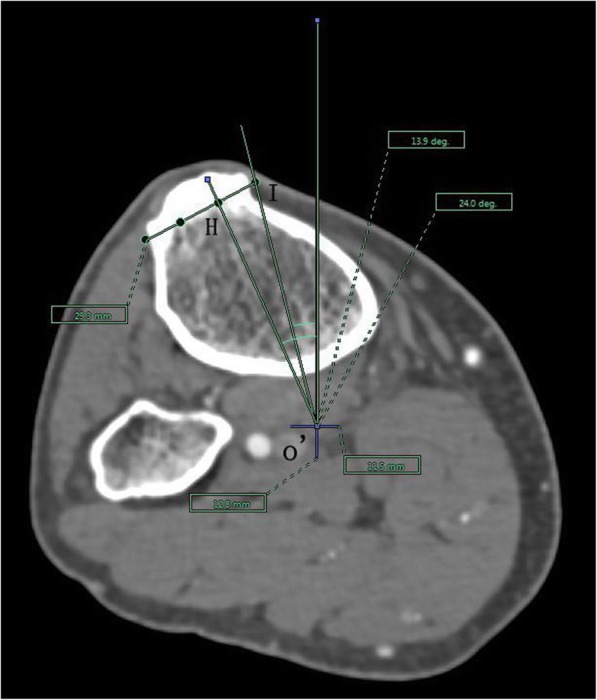
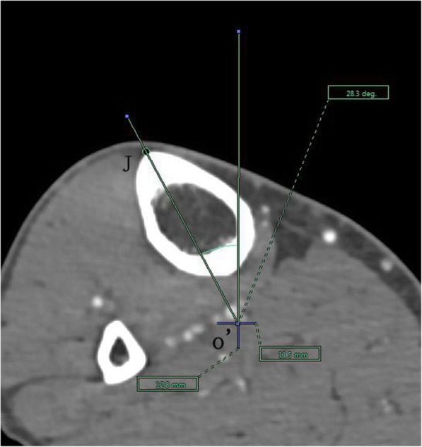
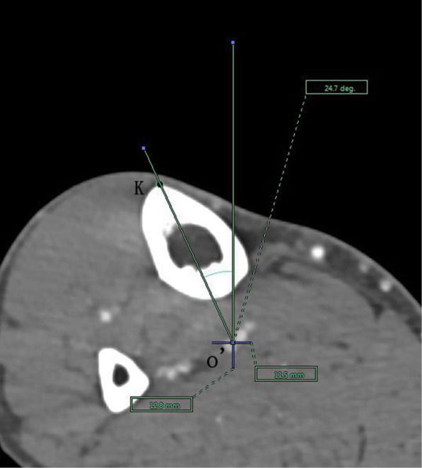
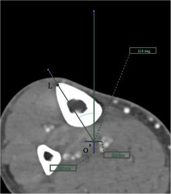
Methods: This study included examination of 122 normal lower extremities. Briefly, 10 axes were drawn on the axial sections: transverse axis of tibia (TAT), axis of medial edge of patellar tendon (MEPT), axis of medial 1/3 of patellar tendon attachment (M1/3), Akagi line, Insall line, axis of medial border of tibial tubercle (MBTT), and axis of anterior border of the tibia 1-4 (ATC1-4). The mean angles between TAT and SEA and that between other axes and the line perpendicular to SEA were measured. Pairwise differences among the 10 tibial axes were examined by applying one-way analysis of variance (ANOVA) and paired t-test.

Results: In all the knees, the mean angles of M1/3, Akagi line, Insall line, MBTT, ATC1, ATC2, ATC3, and ATC4 axes were compared to the line perpendicular to the projected SEA and found to be 10.2 ± 5.1°, 1.4 ± 5.0°, 11.9 ± 5.4°, 3.6 ± 4.8°, 12.0 ± 6.9°, 7.2 ± 8.6°, 7.1 ± 10.4°, and 6.6 ± 13.5° external rotation, respectively, and the MEPT axis was 1.6 ± 4.5° internal rotation. The mean angle for TAT was 4.1 ± 5.3° external rotation. The M1/3 and Insall line were significantly more externally rotated than Akagi line, MEPT, MBTT, TAT, ATC2, ATC3, and ATC4 axes. No significant differences were noted between the TAT axis and the MBTT axis and among the ATC2, ATC3, and ATC4 axes.

Conclusion: The Akagi line, MBTT, and TAT showed good consistency with SEA in the axial femorotibial alignment with knee in extension. The middle segment of the anterior tibial crest also demonstrated good alignment consistency with SEA for the axial femorotibial alignment. Hence, these markers can be used as reliable references for rotational alignment of the tibial component in TKA.

Keywords: Anatomic landmarks; Reference lines; Reliability; Rotational alignment; Tibial component; Total knee arthroplasty.


Conflict of interest statement

The authors declare no competing interests.

Figures

Fig. 1
Fig. 1
Landmarks at 3D reconstruction of the tibia: (1) the point (e) 8-mm distal to the lateral tibial plateau, (2) the medial (b) and lateral border (a) at the level of patellar tendon attachment, and (3) the medial (d) and lateral border (c) at the widest part of the tibial tubercle, (4) isometric marking of 4 points(f1,f2,f3,and f4) along the sharpest margin of the tibial anterior border
Fig. 2
Fig. 2
The surgical epicondylar axis (SEA) was determined by connecting the sulcus of the medial epicondyle and the lateral epicondyle of the femur. The horizontal line represents the horizontal axis of Picture Archiving and Communications Systems (PACS)
Fig. 3
Fig. 3
The medial edge of patellar tendon axis was drawn as a line passing through the middle of the posterior cruciate ligament (PCL) and the medial border of the patellar tendon (MBPT) at a level 8-mm below the lowest point on the lateral plateau. The PCL was recognized clearly in the posterior condylar notch of the tibia. The vertical line represents the vertical axis of PACS
Fig. 4
Fig. 4
The transverse axis of the tibia is defined as the line connecting the midpoint of the medial and lateral tibial condyle at a level 8-mm below the lowest point on the lateral plateau. The horizontal line represents the horizontal axis of PACS
Fig. 5
Fig. 5
Akagi line drawn as a line passing through o’ and G; the medial 1/3 of the patellar tendon axis drawn as a line passing through o’ and F. The vertical line represents the vertical axis of PACS. o’: the projected midpoint of the PCL; G: the medial edge of the patellar tendon attachment; and F: the medial 1/3 of the patellar tendon at the level of the patellar tendon attachment
Fig. 6
Fig. 6
Insall line drawn as a line passing through o’ and H and medial border of tibial tubercle axis drawn as a line passing through o’ and I. The vertical line represents the vertical axis of PACS. o’: the projected midpoint of the PCL; H: the medial 1/3 of tibial tubercle, and I: medial border of tibial tubercle
Fig. 7
Fig. 7
Axes of anterior tibial crest drawn as lines passing through the projected midpoint of the PCL and the 4 points(f1,f2,f3,and f4) pre-labeled on 3D reconstruction of the tibia, respectively. The vertical line represents the vertical axis of PACS. o’: the projected midpoint of the PCL; J: represents f1
Fig. 8
Fig. 8
Axes of anterior tibial crest drawn as lines passing through the projected midpoint of the PCL and the 4 points(f1,f2,f3,and f4) pre-labeled on 3D reconstruction of the tibia, respectively. The vertical line represents the vertical axis of PACS. o’: the projected midpoint of the PCL; K: represents f2
Fig. 9
Fig. 9
Axes of anterior tibial crest drawn as lines passing through the projected midpoint of the PCL and the 4 points(f1,f2,f3,and f4) pre-labeled on 3D reconstruction of the tibia, respectively. The vertical line represents the vertical axis of PACS. o’: the projected midpoint of the PCL; L: represents f3
Fig. 10
Fig. 10
Axes of anterior tibial crest drawn as lines passing through the projected midpoint of the PCL and the 4 points(f1,f2,f3,and f4) pre-labeled on 3D reconstruction of the tibia, respectively. The vertical line represents the vertical axis of PACS. o’: the projected midpoint of the PCL; M: represents f4
Fig. 11
Fig. 11
A boxplot illustrating the distributions of the angles between nine anteroposterior axes of the tibia and the line perpendicular to SEA and the angle between SEA and the transverse axis of the tibia

References

    1. Panni AS, Ascione F, Rossini M, et al. Tibial internal rotation negatively affects clinical outcomes in total knee arthroplasty: a systematic review. Knee Surg Sports Traumatol Arthrosc. 2018;26(6):1636–1644. doi: 10.1007/s00167-017-4823-0. - DOI - PubMed
    1. Keshmiri A, Maderbacher G, Baier C, et al. The influence of component alignment on patellar kinematics in total knee arthroplasty. Acta Orthop. 2015;86(4):444–450. doi: 10.3109/17453674.2015.1005907. - DOI - PMC - PubMed
    1. Steinbrück A, Schröder C, Woiczinski M, et al. Influence of tibial rotation in total knee arthroplasty on knee kinematics and retropatellar pressure: an in vitro study. Knee Surg Sports Traumatol Arthrosc. 2016;24(8):2395–2401. doi: 10.1007/s00167-015-3503-1. - DOI - PubMed
    1. Pang HN, Jamieson P, Teeter MG, McCalden RW, Naudie DD, MacDonald SJ. Retrieval analysis of posterior stabilized polyethylene tibial inserts and its clinical relevance. J Arthroplast. 2014;29(2):365–368. doi: 10.1016/j.arth.2013.05.029. - DOI - PubMed
    1. Asano T, Akagi M, Nakamura T. The functional flexion-extension axis of the knee corresponds to the surgical epicondylar axis: in vivo analysis using a biplanar image-matching technique. J Arthroplast. 2005;20(8):1060–1067. doi: 10.1016/j.arth.2004.08.005. - DOI - PubMed

MeSH terms