. 2020 May 27;11(1):2651.
doi: 10.1038/s41467-020-16437-9.

Ptychography retrieval of fully polarized holograms from geometric-phase metasurfaces

Affiliations

Ptychography retrieval of fully polarized holograms from geometric-phase metasurfaces

Qinghua Song et al. Nat Commun. .

Abstract

Controlling light properties with diffractive planar elements requires full-polarization channels and accurate reconstruction of optical signal for real applications. Here, we present a general method that enables wavefront shaping with arbitrary output polarization by encoding both phase and polarization information into pixelated metasurfaces. We apply this concept to convert an input plane wave with linear polarization to a holographic image with arbitrary spatial output polarization. A vectorial ptychography technique is introduced for mapping the Jones matrix to monitor the reconstructed metasurface output field and to compute the full polarization properties of the vectorial far field patterns, confirming that pixelated interfaces can deflect vectorial images to desired directions for accurate targeting and wavefront shaping. Multiplexing pixelated deflectors that address different polarizations have been integrated into a shared aperture to display several arbitrary polarized images, leading to promising new applications in vector beam generation, full color display and augmented/virtual reality imaging.


Conflict of interest statement

The authors declare no competing interests.

Figures

Fig. 1
Fig. 1. Full-polarization-reconstruction and multi-directional meta-hologram.
a Full-polarization-reconstruction through the superposition of two output CP beams with arbitrary phase and amplitude difference based on the same input LP beams. b Plotted Poincaré sphere covered full polarization with phase difference α from –π to π and amplitude aR and aL from 0 to 1. c Four subpixels of pixelated deflectors (labeled as C1, C2, C3, C4) representing to four SoP (LP-45°, LP-H, RCP, EP) are placed into one super-pixel to share the same aperture. d By encoding the holographic phase profile into the four subpixels array independently, multi-directional holographic images with different SoP are displayed in the direction of θtn=arcsin2φdnk0p (n = 1, 2, 3, 4).
Fig. 2
Fig. 2. Realization of polarization-reconstructed meta-hologram.
a Simulated results of the CP conversion efficiency and relative PB phase of the metasurface consisting of an array of GaN nano-pillars fabricated on the top of a Sapphire substrate. The inset picture shows the schematic of one unit-cell of the metasurface with dimension of Lx = 230 nm, Ly = 120 nm, h = 1 μm, p = 300 nm and various orientation angle φ from 0 to 180°. The incident LCP light is illuminated from the backside. b The scanning electron micrograph (SEM) images of a fabricated meta-hologram, where a top- and tilted-view of enlarged areas in the meta-hologram are presented. The scale bar of the enlarged image is 1 μm. c Structure configuration for the polarization generation of LP-45° (first row), LP-H (second row), RCP (third row), EP (last row). d SEM images of fabricated results. The scale bar is 1 μm. e Photographs of the meta-hologram images representing “alive Schrödinger’s cat”, “dead Schrödinger’s cat”, “CNRS logo 1”, and “CNRS logo 2” with different SoP. High order image is induced near the central spot. f measured SoP of the corresponded images. The red and blue dots on the Poincaré sphere indicate the designed and measured polarization, respectively. Two Schrödingerʼs cats are adapted from Wikimedia.org.
Fig. 3
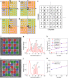
Fig. 3. Uniformly and randomly distributed subpixels.
ad The subpixels in one super-pixel are distributed with four different arrangement. e A 100 × 100 matrix with randomly distributed integer of 1, 2, 3, and 4 is generated using MATLAB. Each numeral is corresponding to the subpixels of (ad). f A beam deflector is designed with subpixels uniformly distributed using configurations shown in (a). The four subpixels C1, C2, C3, and C4 are designed with interested order at 15°, 18.5°, 22°, and 25.5°, respectively. g Measured far-field intensity pattern shows that a series of grating orders βmCn (m = ±1, n = 1, 2, 3, 4) is generated. h Measured angles of the grating orders agree well to the simulated results. i A beam deflector design with randomly distributed subpixels based on the random matrix in (e). j Measured far-field intensity pattern shows the grating order is destroyed due to a variable lattice constant d. k Only interested order is obtained without other grating orders.
Fig. 4
Fig. 4. Realization of polarization-reconstructed meta-hologram with four sub-polarization pixels.
a Schematic of the polarization-reconstructed and multi-directional meta-hologram. b SEM image of the fabricated meta-hologram with uniformly distributed subpixels. c Photograph of the holographic image with a series of ghost images. d SEM image of the fabricated meta-hologram with randomly distributed subpixels. e Photograph of the holographic image with pure desired images. f Close-ups of Jones matrices maps of uniformly distributed and g randomly distributed meta-hologram, with phase encoded as hue and modulus encoded as brightness. Scale bars are 2.2 µm. h Intensity values (arbitrary units), together with the corresponding SoP, of the reconstructed vectorial far field of the metasurface.
Fig. 5
Fig. 5. Polarization characterization of the meta-hologram.
a Polarimeter position at different letters to analyze the SoP. b Measured SoP of the corresponding letters. The red and blue dots indicate the designed and measured polarization, respectively. c A linear polarizer with θLP = 45° and θLP = 90° are put before letter “C” and “N”, respectively. A quarter waveplate with θλ/4 = 0° and a linear polarizer with θLP = 45° are put before letter “R”. A quarter waveplate with θλ/4 = 112.5° and a linear polarizer with θLP = 86° are put before letter “S”. d Photographs of the holographic images indicate that the four letters are blocked correspondently after placing selected polarizer and quarter waveplate.

References

    1. Yu N, et al. Light propagation with phase discontinuities: generalized laws of reflection and refraction. Science. 2011;334:333–337. doi: 10.1126/science.1210713. - DOI - PubMed
    1. Zheng G, et al. Metasurface holograms reaching 80% efficiency. Nat. Nanotechnol. 2015;10:308–312. doi: 10.1038/nnano.2015.2. - DOI - PubMed
    1. Ni X, Wong ZJ, Mrejen M, Wang Y, Zhang X. An ultrathin invisibility skin cloak for visible light. Science. 2015;349:1310–1314. doi: 10.1126/science.aac9411. - DOI - PubMed
    1. Li S-Q, et al. Phase-only transmissive spatial light modulator based on tunable dielectric metasurface. Science. 2019;364:1087–1090. doi: 10.1126/science.aaw6747. - DOI - PubMed
    1. Chen WT, et al. A broadband achromatic metalens for focusing and imaging in the visible. Nat. Nanotechnol. 2018;13:220–226. doi: 10.1038/s41565-017-0034-6. - DOI - PubMed