. 2020 Aug:173:41-49.
doi: 10.1016/j.visres.2020.04.012. Epub 2020 May 25.

Mechanisms underlying simultaneous brightness contrast: Early and innate

Affiliations

Mechanisms underlying simultaneous brightness contrast: Early and innate

Pawan Sinha et al. Vision Res. 2020 Aug.

Abstract

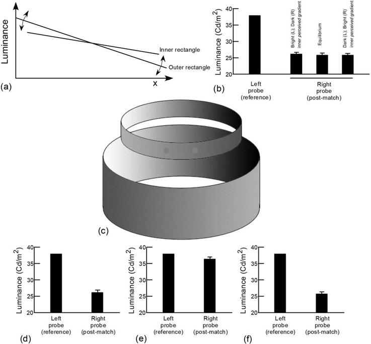
In the phenomenon of simultaneous brightness contrast, two patches, one on a dark background and the other on a light one, appear to have different brightness despite being physically equi-luminant. Elucidating the phenomenon's underlying mechanisms is relevant for the larger question of how the visual system makes photometric judgments in images. Accounts over the past century have spanned low-, mid- and high-level visual processes, but a definitive resolution has not emerged. We present three studies that collectively demonstrate that the computations underlying this phenomenon are low-level, instantiated prior to binocular fusion, and available innately, without need for inferential learning via an individual's visual experience. In our first two studies, we find that strong brightness induction is obtained even when observers are unaware of any luminance differences in the neighborhoods of the probe patches. Results with dichoptic displays reveal that eye of origin, although not evident consciously, has a marked influence on the eventual brightness percept of the probe patches, thereby localizing brightness estimation to a site preceding binocular fusion. The third study uses conventional simultaneous brightness contrast displays, but an unusual group of participants: Congenitally blind children whom we were able to treat surgically. The results demonstrate an immediate susceptibility to the simultaneous brightness illusion after sight onset. Together, these data strongly constrain the search for mechanisms underlying a fundamental brightness phenomenon.

Keywords: Brightness perception; Dichoptic displays; Late sight onset; Nature versus nurture; Simultaneous contrast illusion.


Figures

Figure 1.
Figure 1.
(a) A simultaneous brightness contrast display. The two small discs appear to have different brightness despite having identical luminance. (b) Simultaneous brightness contrast in a real-world setting. The two stones indicated, one in shadow and the other in light, have the same mean luminance, but appear to have different brightness. (c) Display design used in experiment 1. Both rectangles have linear luminance gradients. The magnitude of the outer gradient is fixed (0 to 76 cd/m2) but the inner gradient is under experimental control. The outer gradient induces a change in the brightness profile of the inner strip, with the more luminous side of the outer gradient leading to a perceived darkening of the inner strip. This design of nested rectangles allowed control of the appearance of the inner one. Specifically, the physical gradient of the inner rectangle could interact with the induced gradient from the outer rectangle. We could then study how the brightness of the probe patches was determined by the appearance/physical gradient of the inner rectangle. (d) By setting the inner gradient to precisely null the induced gradient from the surrounding rectangle, the inner strip was made to appear homogenous throughout its length. (e) (Left panel) Two identical probe squares placed within the perceptually uniform strip appear to have very different brightness. (Right panels) Two variations of the display, one with the inner strip removed and the other with the outer rectangle removed. (f) Results from brightness matching experiments performed with the display shown in the left panel of (e). (g) Results with inner strip removed. (h) Results with outer enclosing rectangle removed. Error bars represent +/− 1 standard error.
Figure 2.
Figure 2.
(a) Approach for assessing trade-off between perceived and actual gradients. By changing the gradient magnitude in the enclosing rectangle about the equilibrium state, the inner rectangle can be imparted perceptual brightness gradients in opposite directions while leaving its physical luminance values unchanged. The end points of the gradient were shifted through +/−7.5 cd/m2. (b) Results from brightness matching experiments under three appearances of the inner rectangle: 1. Gradient that is brighter on the left, 2. Perceptual uniformity, and 3. Gradient that is brighter on the right. Brightness matching results stay unchanged across the three conditions. (c) A variant of the display shown in figure 1e. The gradients are now readily interpretable as gradual illumination changes with the light source positioned on the right. The brightness percepts of the two probe dots are unchanged relative to figure 1e. (d) Brightness matching results with the display shown in (c). (e) Matching results after making the outer surface of the top ring black (f) Results after removal of lower ring. Error bars represent +/− 1 standard error.
Figure 3.
Figure 3.
(a) Intensity profile across a conventional Craik-O’ Brien-Cornsweet (COBC) display. (b) The flanks in our display differed from each other so that the side perceived as dark actually had higher luminance than the other. Two identical probes with their luminance set at the mean value of the flanks’ luminances were placed one on each flank. (c) The appearance of the display used in our experiments. The probe on the seemingly lighter flank is perceived as being lighter than the one on the darker flank. (d) Brightness matching results from five participants for three values of inter-flank luminance difference. (e) A variant of the modified COBC display shown in (c). The two fields are now interpreted as differently illuminated faces of a three-dimensional cube. The probe on the right face, which is perceived to be in shadow, is seen as being darker than the other – a result that runs counter to predictions from high-level accounts. (f) Brightness matching results with the COBC display shown in (e). Error bars represent +/− 1 standard error.
Figure 4.
Figure 4.
(a) General appearance of the stereo display used in our experiments. A stereo function allowed a different gradient to be presented to each eye while a subject was wearing NVIDIA 3D Vision stereo goggles. The stimulus was shown to subjects on an ASUS VG278He monitor from a distance of 60 cm. The counter-aligned gradients spanned a luminance range from 33 cd/m2 to 43 cd/m2. The probes had a luminance of 38 cd/m2. The display vertically subtended 10 degrees of visual angle. Subjects were asked to fixate on the red cross. The luminance gradients in this image have been enhanced for the purpose of exposition. (b) Temporal structure of each trial. The solid black lines in each panel represent image intensity profiles. A trial began with the basic stereo display showing the two strips. Next, a pair of equi-luminant probe discs were transiently superimposed on one of the stereo-half images. (c, d) Percepts obtained with oppositely directed luminance gradients equal (c) or unequal (d) in magnitude are qualitatively consistent with binocular averaging accounts. (d) With two iso-directed gradients, the binocular averaging account predicts brightness percepts that are at odds with the actual percept obtained. As shown in the schematic profiles, the averaging account predicts the relative brightness of the two probes to be in the opposite direction from what is actually perceived. (Note that in the schematic for the obtained percept in panels c and d, we have not indicated a gradient within the probes because the subjects’ task was simply to report the relative brightness of the two probes.)
Figure 5.
Figure 5.
(a) Displays used in our studies with newly-sighted children. For each display, children had to indicate which of the two small discs appeared darker. Discs in two displays (here the two leftmost ones) had a physical luminance difference. Disc pairs in the remaining displays were equiluminant. (b) Results from newly sighted and controls on seven displays. In each display, the two probes were arbitrarily labeled ‘A’ and ‘B’ for result recording (subjects were unaware of this labeling). The plots show percent of controls and newly sighted who chose one or the other probe as being brighter. Notably, the choices are almost entirely concordant across the two groups.

References

    1. Adelson EH (1993) Perceptual organization and the judgment of brightness. Science, 262:2042–2044. - PubMed
    1. Adelson EH (2000). “Lightness perception and lightness illusions,” in The New Cognitive Neurosciences, ed Gazzaniga M, editor. Cambridge, MA: MIT Press, 339–351.
    1. Agostini T, Proffitt DR (1993) Perceptual organization evokes simultaneous lightness contrast. Perception, 22:263–272. - PubMed
    1. Agostini T, & Galmonte A (2002). Perceptual organization overcomes the effect of local surround in determining simultaneous lightness contrast. Psychological Science, 13(1), 88–92. - PubMed
    1. Agrillo C, Miletto Petrazzini ME, & Bisazza A (2016). Brightness illusion in the guppy (Poecilia reticulata). Journal of Comparative Psychology, 130(1), 55–61. - PubMed

Publication types