Review
. 2020 May 29;12(6):1237.
doi: 10.3390/polym12061237.

Advances in the Research of Bioinks Based on Natural Collagen, Polysaccharide and Their Derivatives for Skin 3D Bioprinting

Affiliations
Review

Advances in the Research of Bioinks Based on Natural Collagen, Polysaccharide and Their Derivatives for Skin 3D Bioprinting

Jie Xu et al. Polymers (Basel). .

Abstract

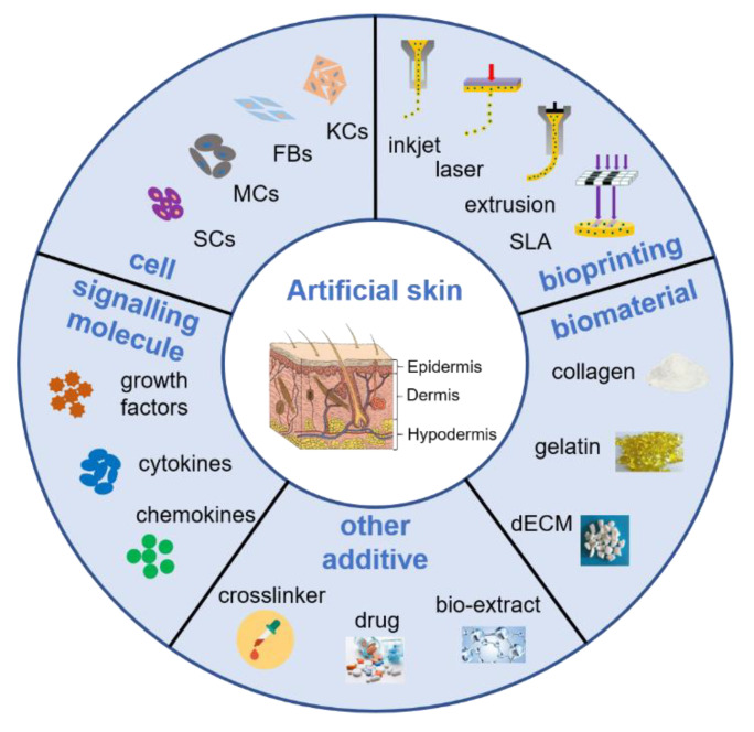
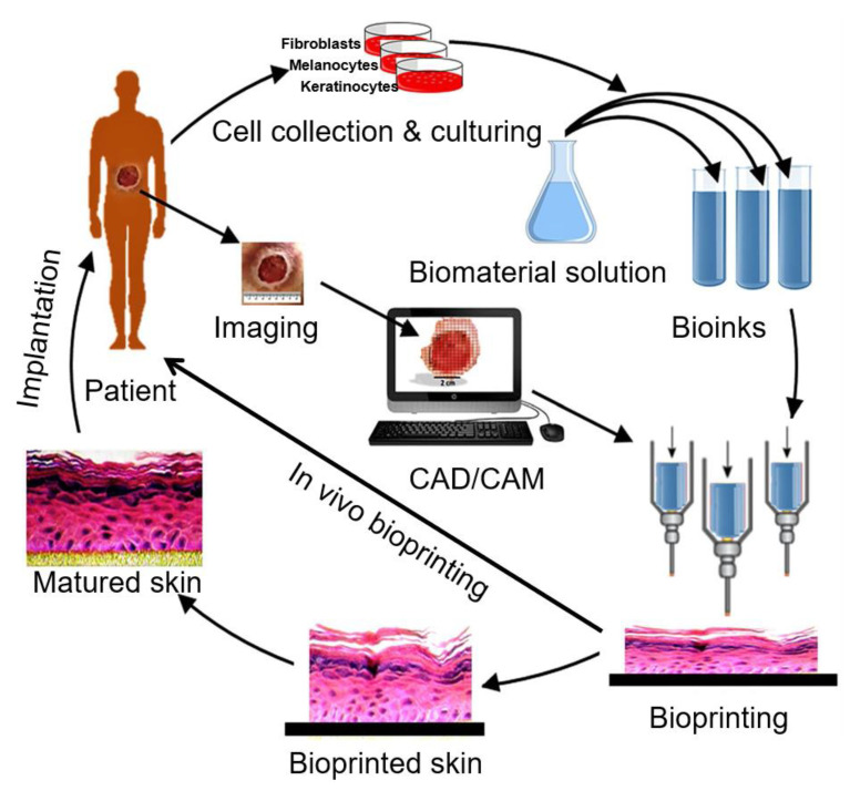
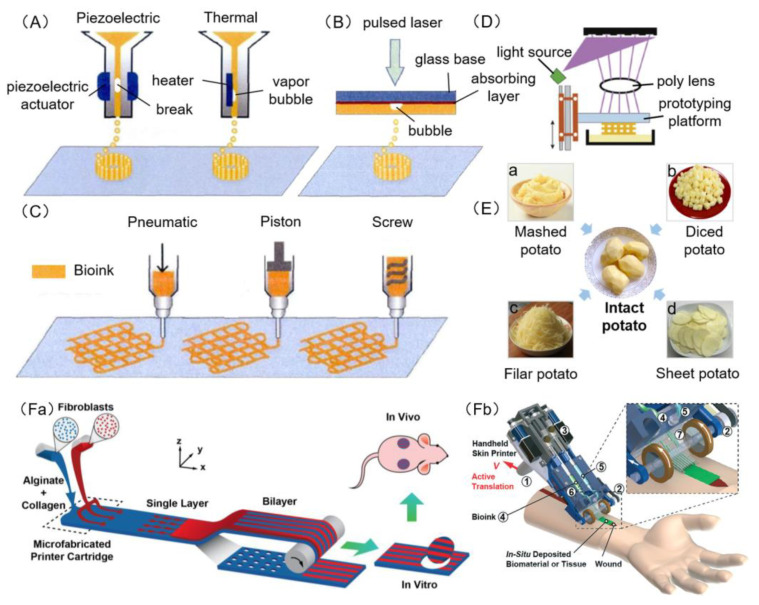
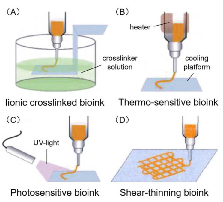
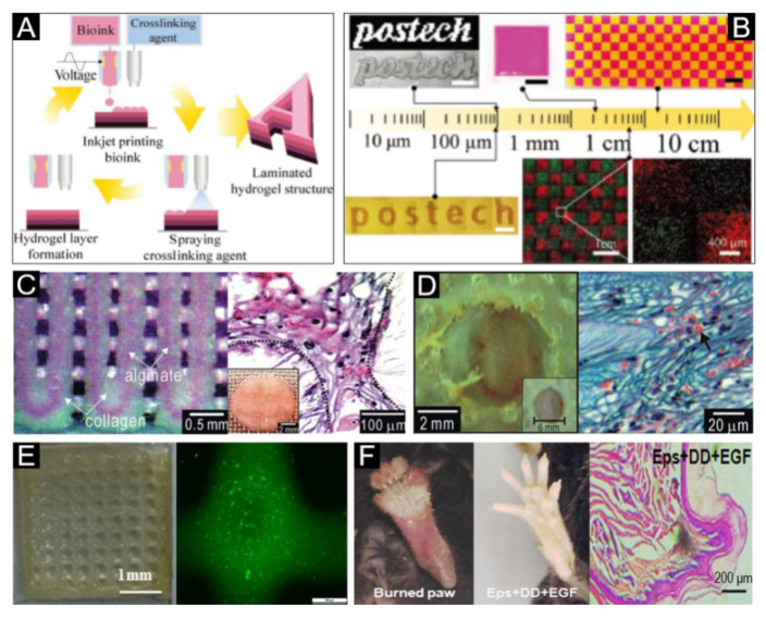
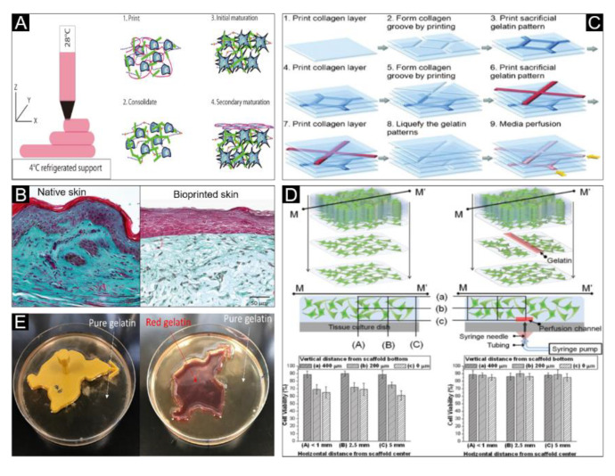
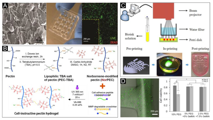
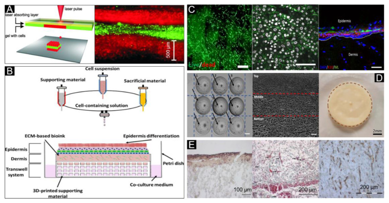
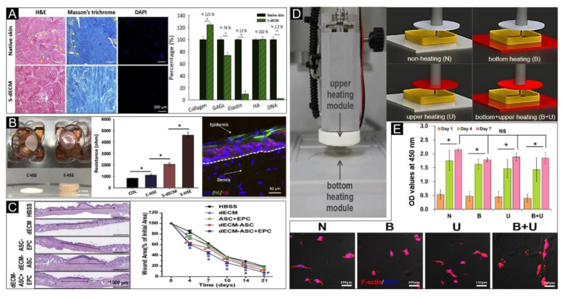
The skin plays an important role in protecting the human body, and wound healing must be set in motion immediately following injury or trauma to restore the normal structure and function of skin. The extracellular matrix component of the skin mainly consists of collagen, glycosaminoglycan (GAG), elastin and hyaluronic acid (HA). Recently, natural collagen, polysaccharide and their derivatives such as collagen, gelatin, alginate, chitosan and pectin have been selected as the matrix materials of bioink to construct a functional artificial skin due to their biocompatible and biodegradable properties by 3D bioprinting, which is a revolutionary technology with the potential to transform both research and medical therapeutics. In this review, we outline the current skin bioprinting technologies and the bioink components for skin bioprinting. We also summarize the bioink products practiced in research recently and current challenges to guide future research to develop in a promising direction. While there are challenges regarding currently available skin bioprinting, addressing these issues will facilitate the rapid advancement of 3D skin bioprinting and its ability to mimic the native anatomy and physiology of skin and surrounding tissues in the future.

Keywords: 3D bioprinting; bioink; skin regeneration; skin tissue engineering; wound healing.


Conflict of interest statement

The authors have no conflict of interest.

Figures

Figure 1
Figure 1
Schematic representation of the main requirements related to 3D bioprinting for skin regeneration. The artificial skin was printed by inkjet, laser, extrusion or stereolithography (SLA) bioprinting technologies with a cell-encapsulating bioink, which consists of biomaterials, constituent cells, stem cells and signaling molecules, or acellular bioink which contains biomaterials only. The mechanical property of artificial skin was enhanced by adding crosslinker, and some drugs or bio-extract were adding to obtain multifunctional skin for wound healing, such as anti-inflammatory and antibacterial. Abbreviations: KCs: Keratinocytes, FBs: Fibroblasts; MCs: Melanocytes, SCs: Stem cells, dECM: Decellularized extracellular matrix.
Figure 2
Figure 2
The basic process of 3D bioprinting skin. Various cells like keratinocytes, fibroblasts and melanocytes are collected from the patient and cultured in a cell culture system. A suitable biomaterial is mixed with the cells and the formed bioink is fed to the bioprinting system. Then the skin is printed with appropriate 3D bioprinting technology according to the 3D pattern that is captured from the wound using CAD/CAM approaches. The printed skin could be directly printed to the wound surface or cultured under appropriate conditions to obtain mature skin for transplantation. Adapted from [22], under open access license.
Figure 3
Figure 3
Schematic diagram of 3D bioprinting. (A) Piezoelectric inkjet bioprinters form pulses by piezoelectric pressure to force droplets from the nozzle, while thermal bioprinters use air-pressure pulses produced by a printhead that is electrically heated. (B) Laser bioprinters use laser focused on an absorbing substrate to generate pressures that propel bioink onto a collector substrate. (C) Extrusion bioprinters use pneumatic, piston or screw dispensing systems to extrude continuous beads of bioink. (D) Stereolithography bioprinters use a digital light projector to selectively crosslink bioink plane-by-plane. Images (A)–(D) were adapted with permission from [66]; copyright Journal of Zhejiang University (Engineering Science), 2019. (E) Schematic diagram of traditional 3D bioprinting similar to the reverse process of cutting potatoes; laser (B), inkjet (A), extrusion (C), stereolithography (D) bioprinting seem like the assembling of potatoes from mashed potato (a), diced potato (b), filar potato (c) and sheet potato (d), respectively. (F) Microfluidic bioprinters use a microfluidic-based device to extrude a biopolymer sheet with precise spatio-temporal control over the component proportion of bioink. (a) Illustration of proposed skin printer for formation of cell-populated skin substitute in a microfabricated printer cartridge and application in vivo. Image (Fa) was reproduced with permission from [51]; copyright Chemical and Biological Microsystems Society, 2013. (b) Rendered image of handheld bioprinter. ① a handle, ② a stepper motor to define the deposition speed, ③ two on-board syringe pump modules controlling the flow rates of bioink and cross-linker solution, ④ bioink, ⑤ cross-linker solution, ⑥ syringe holder, ⑦ 3D printed microfluidic cartridge for spatial organization of solutions and sheet formation. Image (Fb) was reproduced with permission from [65]; copyright Royal Society of Chemistry, 2018.
Figure 4
Figure 4
Four common types of bioink. (A) Ionic crosslinking bioink mainly performs the solidification through ionic crosslinking reaction. (B) Thermo-sensitive bioink mainly performs the transformation from sol to gel state by heating or cooling. (C) Photosensitive bioink mainly performs the transformation from sol to gel state by activating the light initiator in bioink. (D) Shear-thinning bioink mainly performs the solidification through shear force. The viscosity of some materials decreases with the increase of shear stress, while gelation on the platform occurs with no shear stress. Adapted with permission from [66]; copyright Journal of Zhejiang University (Engineering Science), 2019.
Figure 5
Figure 5
Ionic crosslinked bioink for skin bioprinting. (A) Schematic of the inkjet-spray printing process for the fabrication of laminated hydrogel structures. (B) Inkjet-spray-printed hydrogel structures of various scales, ranging from several hundreds of micrometers to a few tens of centimeters. The results indicated a high cell viability on the hydrogel structure. Reproduced with permission from [93]; copyright Wiley-VCH, 2018. (C) The optical image (Left) and optical cross-section image stained with hematoxylin and eosin (Right) of the fabricated core/shell scaffold. (D) The optical image (Left) and histological photomicrograph of the wound cross-section. Arrowheads indicate the generated vasculature. Reproduced with permission from [150]; copyright Royal Society of Chemistry, 2011. (E) Representative image (Left) of the cell-laden printed construct and fluorescence image (Right) of cells embedded in the printed construct. (F) Sweat gland regeneration (Middle) and histology of wound healing (Right) in mouse paw after 3D-ECM mimics implantation; the burned mouse paw is shown on the left. Reproduced with permission from [82]; copyright Elsevier, 2015.
Figure 6
Figure 6
Thermo-sensitive bioink for skin bioprinting. (A) Schematic representation of the 3D bioprinting, consolidation and maturation steps using the developed bioink. (B) Histological and morphological characterization of native skin and the bioprinted skin. Reproduced with permission from [152]; copyright Wiley-VCH, 2016. (C) Schematic procedure of the construction of the multi-layered collagen scaffold with embedding and removal of sacrificial gelatin patterns using the 3D bio-printer. (D) Top: Schematics of fibroblast (FB)-laden collagen scaffold construction without (top, left) and with (top, right) embedding and removal of printed sacrificial gelatin channel. Middle: FB viability inspected locations (a vertical section at M–M’) in the collagen scaffolds without (middle, left) and with (middle, right) inside media perfusion. Bottom: Measured FB viability at the inspected locations after 1 week of culture without and with media perfusion. Reproduced with permission from [153]; copyright Wiley Periodicals, 2009. (E) Cast pure gelation and red gelatin placed in 4 °C for gelation. Reproduced with permission from [27]; copyright Elsevier, 2018.
Figure 7
Figure 7
Photosensitive bioink for skin bioprinting. (A) Microstructure (left) and image (middle) of the pectin hydrogel with optimal crosslinker, and confocal microscopy image (right) of fibroblasts live/dead staining, which indicated high cell viability embedded within the 3D porous construct. Reproduced with permission from [156]; copyright Royal Society of Chemistry, 2013. (B) Schematic illustration of photocrosslinking and biofunctionalization of click NorPEC hydrogels via UV light. Reproduced with permission from [114]; copyright Elsevier, 2017. (C) Schematic diagram of developed visible light stereolithography-based bioprinting system and bioprinting procedure of the developed system. (D) Qualitative and quantitative cell viability analysis of fibroblasts within the printed structure. Reproduced with permission from [158]; copyright IOP, 2015.
Figure 8
Figure 8
Shear-thinning bioink for skin bioprinting. (A) Sketch of the laser printing setup (left) and the alternating color-layers of red (keratinocytes) and green (fibroblasts) (right). Reproduced with permission from [83]; copyright Wiley Periodicals, 2012. (B) Extrusion-inkjet printing pattern for fabrication of 3D printed human skin model and its maturation with functional transwell system, all in a single-step process. (C) Image and dead images of the contracted compartments at day 7 to reveal their morphology and viability (left, scale bar: 200 μm), immunofluorescence labelling examination of E-cadherin (middle, white: Nuclei, green: E-cadherin, scale bar: 200 μm), and immunofluorescence analysis of the human skin model (Right, DAPI: Nucleus, K10: Early differentiation marker, and IVL: Involucrin, scale bar: 100 μm). Reproduced with permission from [160]; copyright IOP, 2017. (D) A two-step 3D bioprinting strategy to manipulate the cell distribution (cells indicated by black arrows—homogeneous cell distribution) (Left), pore size distribution with the 3D collagen matrix-hierarchical porous microstructure (middle), and 3D bioprinted pigmented human skin constructs with uniform skin pigmentation (right), pigmented area is enclosed by the brown dotted line. Reproduced with permission from [116]; copyright IOP, 2018. (E) E-cadherin expression (left), blood vessels (arrows) (middle) and collagen IV (right) can be detected in the skin constructs on day 11. Reproduced from [161], under open access license.
Figure 9
Figure 9
Decellularized extracellular matrix (dECM) bioink for skin bioprinting. (A) Qualitative analysis with H&E, Masson’s trichrome and DAPI staining (left) and quantitative analysis (right) of skin-derived dECM bioink, including collagen, GAGs, elastin, hyaluronic acid and DNA, which indicated that it successfully removes the cellular components from the native skin tissue. (B) Representative photographs (left) of 3D cell-printed in vitro skin equivalents, electrical resistance values for each group (S-HSE is the group using skin-derived dECM bioink, and the others are control group) (middle) and protein expressions (right) of the S-HSE group on day 10 after ALI culture. Involucrin (IVL): Early epidermal differentiation marker; keratin 10 (K10): Late epidermal differentiation marker. (C) Representative photographs of skin wound tissues on day 21 (wound gap, black lines exhibit distances between advancing edges of wounds) (left) and wound areas relative to the orginal ones, indicating the bioprinted skin based on dECM bioink accelerated wound healing. Reproduced with permission from [122]; copyright Elsevier, 2018. (D) Photographs of the upper and bottom heating modules installed in 3D printing equipment (left), and conceptual diagram of non-heating and heating conditions (right). (E) Qualitative (bottom) and quantitative (upper) analysis of cellular activities under different heating conditions. Reproduced from [23], under open access license.

References

    1. Velasquillo C., Galue E.A., Rodriquez L., Ibarra C., Ibarra-Ibarra L.G. Skin 3D bioprinting. Applications in cosmetology. J. Cosm. Dermatol. Sci. Appl. 2013;3:85–89. doi: 10.4236/jcdsa.2013.31A012. - DOI
    1. Coyer F., Gardner A., Doubrovsky A., Cole R., Ryan F.M., Allen C., McNamara G. Reducing pressure injuries in critically ill patients by using a patient skin integrity care bundle (InSPiRE) Am. J. Crit. Care. 2015;24:199–209. doi: 10.4037/ajcc2015930. - DOI - PubMed
    1. Peck M.D. Epidemiology of burns throughout the world. Part I: Distribution and risk factors. Burns. 2011;37:1087–1100. doi: 10.1016/j.burns.2011.06.005. - DOI - PubMed
    1. Yildirimer L., Thanh N.T., Seifalian A.M. Skin regeneration scaffolds: A multimodal bottom-up approach. Trends Biotechnol. 2012;30:638–648. doi: 10.1016/j.tibtech.2012.08.004. - DOI - PubMed
    1. Pereira R.F., Barrias C.C., Granja P.L., Bartolo P.J. Advanced biofabrication strategies for skin regeneration and repair. Nanomedicine. 2013;8:603–621. doi: 10.2217/nnm.13.50. - DOI - PubMed

LinkOut - more resources