. 2020 Jun;7(2):021406.
doi: 10.1063/1.5144808.

Fast transformation of 2D nanofiber membranes into pre-molded 3D scaffolds with biomimetic and oriented porous structure for biomedical applications

Affiliations

Fast transformation of 2D nanofiber membranes into pre-molded 3D scaffolds with biomimetic and oriented porous structure for biomedical applications

Shixuan Chen et al. Appl Phys Rev. 2020 Jun.

Abstract

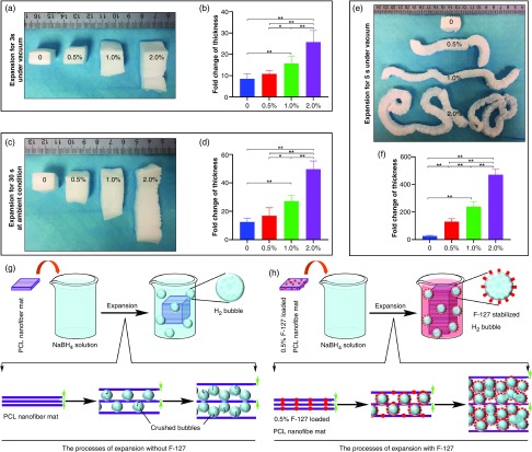
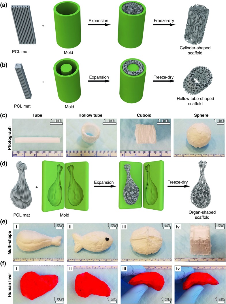
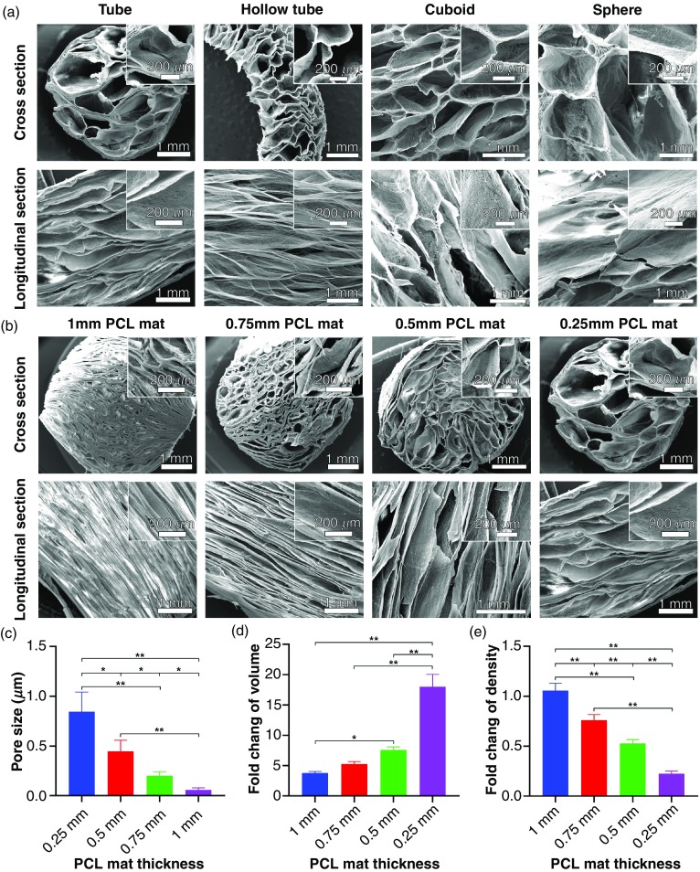
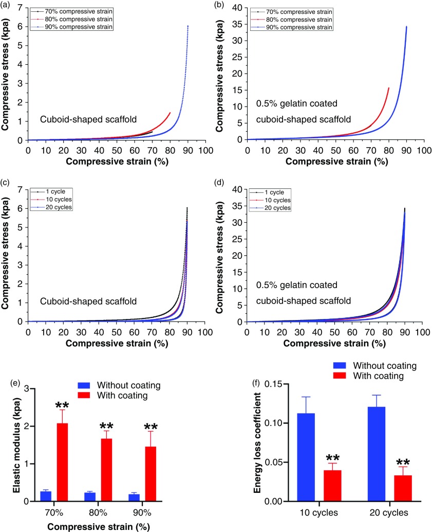
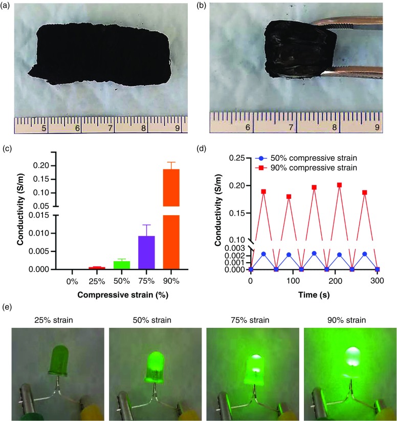
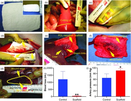
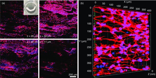
The ability to transform two-dimensional (2D) structures into three-dimensional (3D) structures leads to a variety of applications in fields such as soft electronics, soft robotics, and other biomedical-related fields. Previous reports have focused on using electrospun nanofibers due to their ability to mimic the extracellular matrix. These studies often lead to poor results due to the dense structures and small poor sizes of 2D nanofiber membranes. Using a unique method of combining innovative gas-foaming and molding technologies, we report the rapid transformation of 2D nanofiber membranes into predesigned 3D scaffolds with biomimetic and oriented porous structure. By adding a surfactant (pluronic F-127) to poly(ε-caprolactone) (PCL) nanofibers, the rate of expansion is dramatically enhanced due to the increase in hydrophilicity and subsequent gas bubble stability. Using this novel method together with molding, 3D objects with cylindrical, hollow cylindrical, cuboid, spherical, and irregular shapes are created. Interestingly, these 3D shapes exhibit anisotropy and consistent pore sizes throughout entire object. Through further treatment with gelatin, the scaffolds become superelastic and shape-recoverable. Additionally, gelatin-coated, cube-shaped scaffolds were further functionalized with polypyrrole coatings and exhibited dynamic electrical conductivity during cyclic compression. Cuboid-shaped scaffolds have been demonstrated to be effective for compressible hemorrhage in a porcine liver injury model. In addition, human neural progenitor cells can be uniformly distributed and differentiated into neurons throughout the cylinder-shaped nanofiber scaffolds, forming ordered 3D neural tissue constructs. Taken together, the approach presented in this study is very promising in the production of pre-molded 3D nanofiber scaffolds for many biomedical applications.


Figures

FIG. 1.
FIG. 1.
The effect of the additive surfactant pluronic F127 (F-127) on the expansion of PCL nanofiber mats. (a) Photographs showing the morphology of PCL nanofiber mats and 0.5%, 1%, and 2% F-127 loaded PCL nanofiber mats that were pre-expanded in 1 M NaBH4 solution for 3 s under vacuum condition. (b) The lengths fold changes of the length after pre-expansion (3 s before expansion). (c) Photographs showing the morphology of pre-expanded nanofiber mats in (a) that were sequentially expanded in 1 M NaBH4 solution for 30 s at ambient condition. (d) The lengths fold changes of the length after expansion and 30 s before expansion. (e) Photographs showing the morphology of expanded nanofiber mats in (a,c) that were expanded in 1 M NaBH4 solution for 35 s under vacuum, then freeze-dried conditions. (f) The length fold changes of the final length of scaffold after freeze-dry and before expansion. 0: PCL nanofiber mats. 0.5%: 0.5% F-127 loaded PCL nanofiber mats. 1.0%: 1% F-127 loaded PCL nanofiber mats. 2.0%: 2% F-127 loaded PCL nanofiber mats. (n = 5, *p < 0.05, **p < 0.01). (g) Schematic illustrating the expansion process of PCL nanofiber mats without addition of F-127. The H2 bubbles tend to escape. (h) Schematic illustrating the expansion process of PCL nanofiber mats with addition of F-127. The F-127 additive enhances the hydrophilicity and water penetration of PCL nanofiber mats and, meanwhile, the H2 bubbles are stabilized by F-127 molecules, resulting in a faster expansion. Two green arrows indicate the gap between nanofiber layers.
FIG. 2.
FIG. 2.
Fast transformation of 2D nanofiber mats into pre-molded 3D scaffolds with oriented porous structure. Schematic illustrating the procedure of converting a 2D nanofiber mat into a cylinder-shaped nanofiber scaffold (a) and hollow tube-shaped scaffold (b) by expanding the mat in customized molds. (c) Photographs of transformed, cylinder-shaped, hollow tube-shaped, cuboid-shaped, and sphere-shaped nanofiber scaffolds. 3D nanofiber scaffolds with irregular shapes produced through confined expansion in irregular spaces. (d) Schematic illustrating the procedure of converting a 2D nanofiber mat into an irregular-shaped nanofiber scaffold by expanding the mat in a customized, irregular-shaped mold. (e) The photographs showing the transformed 3D scaffolds with chicken leg-like shape (i), fish-like shape (ii), bread-like shape, (iii) and castle-like shape (iv). (f) The photographs showing the top view (i), bottom view (ii), and side view (ii and iv) of a 3D scaffold with human liver-like shape. The fibers were stained with 1% (w/v) rhodamine 6 G in red.
FIG. 3.
FIG. 3.
The internal structure characterization of confined, expanded nanofiber scaffolds. (a) SEM images showing cross section and longitudinal section of cylinder-shaped, hollow tube-shaped, cuboid-shaped, and sphere-shaped scaffolds. Cylinder-shaped nanofiber scaffolds with tunable pore sizes and porosities. (b) SEM images showing the cross section and longitudinal section of cylinder-shaped nanofiber scaffolds expanded from fiber mats that are 1 mm, 0.75 mm, 0.5 mm, and 0.25 mm thick. Insets: the corresponding magnified images. Pore sizes (c), relative volume change (volume of scaffold after expansion/volume of nanofiber mat), and (d) relative density fold change (density of scaffold after expansion/density of nanofiber mat) (e) of cylinder-shaped nanofiber scaffolds expanded from fiber mats with different thicknesses. *p < 0.05, **p < 0.01.
FIG. 4.
FIG. 4.
Mechanical property of transformed 3D nanofiber scaffolds. (a) Compressive tests of cuboid-shaped nanofiber scaffolds (dimension: 20 mm × 10 mm × 10 mm) under 70%, 80%, and 90% compressive strains. (b) Compressive tests of 0.5% gelatin-coated, cuboid-shaped nanofiber scaffolds under 70%, 80%, and 90% compressive strains (the 70% compression curve is behind the 80% compression curve). (c) Cyclic compressive tests of cuboid-shaped nanofiber scaffolds under 90% compressive strain (1, 10, and 20 cycles). (d) Cyclic compressive tests of 0.5% gelatin-coated, cuboid-shaped nanofiber scaffolds under 90% compressive strain (1, 10, and, 20 cycles). (e) Elastic modulus of cuboid-shaped nanofiber scaffolds with and without 0.5% gelatin coating under different compressive strains. (f) Energy loss coefficients of cuboid-shaped nanofiber scaffolds with and without 0.5% gelatin coating under different compressive strains. **p < 0.01.
FIG. 5.
FIG. 5.
Functionalization of transformed 3D 0.5% F-127/PCL nanofiber scaffolds. (a) The photograph of a polypyrrole-coated 0.5% F-127/PCL nanofiber scaffold. (b) The inside view of a polypyrrole-coated 0.5% F-127/PCL nanofiber scaffold. (c) The electrical conductivity of polypyrrole-coated, 0.5% F-127/PCL nanofiber scaffolds under 25%, 50%, 75%, and 90% compressive strains. (d) The cyclic conductivity of transformed, polypyrrole-coated, 0.5% F-127/PCL nanofiber scaffolds under 50% and 90% compressive strains (5 cycles). (e) A battery-powered circuit (3 V) was used to demonstrate different conductivities of polypyrrole-coated 3D nanofiber scaffolds under 25%, 50%, 75%, and 90% compressive strains.
FIG. 6.
FIG. 6.
The hemostatic application of transformed, cuboid-shaped 0.5% F-127/PCL nanofiber scaffolds in a porcine model of liver resection. (a) The top and side (inset) views of cuboid-shaped 0.5% F-127/PCL nanofiber scaffolds. (b) Left medial lobe resection performed along the indicated dots line. (c) Bimanual compression of nanofiber scaffolds against the resection site with hands for 5 min. (d) Injury site covered with PCL nanofiber scaffolds immediately after the 5 min period of bimanual compression, hemorrhage has stopped. (e) Liver ex vivo after the 1 h observation period; and the nanofiber scaffold bandage is adherent to the injury site. (f) The nanofiber scaffold after it was peeled away from the injury site. (g) The injury site after the nanofiber scaffold was peeled off. (h,i) The quantification of blood loss (h) and artery pressure (i) for the control (untreated group) and nanofiber scaffold treatment groups after 60 min. (n = 3, *p < 0.05, **p < 0.01).
FIG. 7.
FIG. 7.
In vitro culture of hNSCs on transformed, cylinder-shaped nanofiber scaffolds (4 cm in length, 3 mm in diameter, initial fiber mat thickness = 0.5 mm). (a) Cell distribution of human neural progenitor cells in different depths of cylinder-shaped nanofiber scaffolds after neuronal differentiation for 14 days. Inset: a photograph showing a transformed, cylinder-shaped nanofiber scaffold seeded with hNSCs. (b) The 3D confocal microscopy image showing the formation of 3D neuronal networks inside the scaffold after neuronal differentiation for 14 days. Cells were stained with Tuj 1 for neurons in red, and cell nuclei were stained with DAPI in blue.

References

    1. Xu S., Yan Z., Jang K. I., Huang W., Fu H., Kim J., Wei Z., Flavin M., McCracken J., Wang R., Badea A., Liu Y., Xiao D., Zhou G., Lee J., Chung H. U., Cheng H., Ren W., Banks A., Li X., Paik U., Nuzzo R. G., Huang Y., Zhang Y., and Rogers J. A., Science 347(6218), 154 (2015).10.1126/science.1260960 - DOI - PubMed
    1. Moon H., Chou N., Seo H. W., Lee K., Park J., and Kim S., ACS Appl. Mater. Interfaces 11(39), 36186 (2019).10.1021/acsami.9b09578 - DOI - PubMed
    1. Fan D., Lee B., Coburn C., and Forrest S. R., Proc. Natl. Acad. Sci. U. S. A. 116(10), 3968 (2019).10.1073/pnas.1813001116 - DOI - PMC - PubMed
    1. Nan K., Luan H., Yan Z., Ning X., Wang Y., Wang A., Wang J., Han M., Chang M., Li K., Zhang Y., Huang W., Xue Y., Huang Y., Zhang Y., and Rogers J. A., Adv. Funct. Mater. 27(1), 1604281 (2017).10.1002/adfm.201604281 - DOI - PMC - PubMed
    1. Fu H., Nan K., Bai W., Huang W., Bai K., Lu L., Zhou C., Liu Y., Liu F., Wang J., Han M., Yan Z., Luan H., Zhang Y., Zhang Y., Zhao J., Cheng X., Li M., Lee J. W., Liu Y., Fang D., Li X., Huang Y., Zhang Y., and Rogers J. A., Nat. Mater 17(3), 268 (2018).10.1038/s41563-017-0011-3 - DOI - PMC - PubMed

LinkOut - more resources