Review
. 2020 Jul;93(1111):20200113.
doi: 10.1259/bjr.20200113. Epub 2020 Jun 15.

A half-century of innovation in technology-preparing MRI for the 21st century

Affiliations
Review

A half-century of innovation in technology-preparing MRI for the 21st century

Peter Börnert et al. Br J Radiol. 2020 Jul.

Abstract

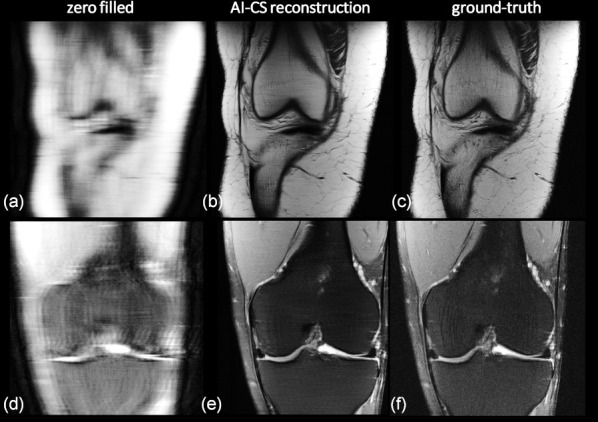
MRI developed during the last half-century from a very basic concept to an indispensable non-ionising medical imaging technique that has found broad application in diagnostics, therapy control and far beyond. Due to its excellent soft-tissue contrast and the huge variety of accessible tissue- and physiological-parameters, MRI is often preferred to other existing modalities. In the course of its development, MRI underwent many substantial transformations. From the beginning, starting as a proof of concept, much effort was expended to develop the appropriate basic scanning technology and methodology, and to establish the many clinical contrasts (e.g., T1, T2, flow, diffusion, water/fat, etc.) that MRI is famous for today. Beyond that, additional prominent innovations to the field have been parallel imaging and compressed sensing, leading to significant scanning time reductions, and the move towards higher static magnetic field strengths, which led to increased sensitivity and improved image quality. Improvements in workflow and the use of artificial intelligence are among many current trends seen in this field, paving the way for a broad use of MRI. The 125th anniversary of the BJR is a good point to reflect on all these changes and developments and to offer some slightly speculative ideas as to what the future may bring.


Figures

Figure 1.
Figure 1.
Schematic evolution of the MRI system. (a) Scheme of a basic single channel transmit/receive system (Tx/Rx) used for MR spectroscopy. A corresponding proton spectrum is given which can be visualised via the user interface (UI) running on the host computer of the system. Please note, human-size systems of this kind existed only as prototypes. However, the technical roots of early MR imagers were in MR spectroscopy equipment used for chemical and structural analysis. (b) Scheme of an early MRI scanner with a three-dimensional gradient system added for spatial encoding (GA denotes the three gradient amplifiers). An early human head image added. (c) Basic MRI extended with parallel reception (please see the multiple Rx channels) with a Turbo Spin Echo (TSE) image obtained with an eight-channel head coil. (d) Scheme of a modern high-field MRI additionally equipped with a parallel transmission system to mainly homogenise the transmit RF field. A dual-transmit channel RF-shimmed 3T body image added for illustration. Additionally, the reconstruction is schematically highly parallelised to keep track with the increased reconstruction demands of parallel imaging and compressed sensing. So, in general, a clear trend of parallelisation becomes visible, on the reception, the transmission and the reconstruction side. Please note that the triangles represent the amplifiers present in the corresponding chains. The small black triangles denote the MR signal pre-amplifiers, whereas the big ones mark the RF amplifiers present in the Tx chain. The large grey triangles mark the gradient amplifiers.
Figure 2.
Figure 2.
The evolution of MRI sampling schemes. Illustrated using 2D k-space sampling patterns. (a) Shows a radial scheme, the one MRI actually started with. (b) Cartesian sampling which took over due to its simplicity and robustness against hardware imperfections. (c) Spiral k-space sampling which maximises the sampling efficiency. (d) Hybrid radial–Cartesian sampling which is motion robust (each blade allows low resolution motion navigation). (e,f) Sub-sampling schemes for the dominant Cartesian schemes: (e) uniform sub-sampling as used in parallel imaging applications like SENSE and (f) variable density sub-sampling. A partially uniform version of (f) is used in GRAPPA while a more random version is used for compressed sensing.
Figure 3.
Figure 3.
Selected MR contrasts and different anatomies for illustration. In the top row, different brain images are shown among them are T1T2 weighted images, a fluid-attenuated inversion recovery (FLAIR), an MR angiogram, an inversion recovery (IR) image, a single shot diffusion scan (spiral, b = 1000 s/mm²) and a fractional anisotropy (FA) map showing fibre anisotropy. The middle row shows a reformatted coronary angiogram, an amide proton transfer (APT) map in a tumour patient, two Dixon images (water only, water-fat in-phase), a diffusion-weighted whole-body image with background body signal suppression (DWIBS), a column of three single diffusion images (b-values 0, 100, 1000 s/mm²) and a spine T2 weighted image. In the bottom row, a flow-resolved cardiac image, a cardiac T1 map to judge contrast media uptake quantitatively and two further Dixon images (water-fat out-phase, fat only) are shown.
Figure 4.
Figure 4.
Comparison SENSE and compressed SENSE. Slices of a retrospectively under-sampled 3D T2 weighted TSE data set reconstructed with different acceleration factors and sampling methods (SENSE/Compressed SENSE) using a 15-element head coil (voxel 1.0×1.0×1.2 mm³, 3T). Formally the 4×4 accelerated case is already under-determined. The advantage of variable density sampling and compressed sensing reconstruction over SENSE is obvious. Please note that there is no claim that the 4×4 variable density CS image is of clinical diagnostic value.
Figure 5.
Figure 5.
Accelerating MRI using an iterative AI/deep learning-based compressed-sensing approach. Clinical knee data (arXiv 1811.08839, 2018) measured with a 15-channel knee coil at two different contrasts were retrospectively variable density under-sampled and reconstructed. (a,d) Using zero filling, Fourier transform and coil image combination, (b,e) by an iterative AI-CS approach, whereas (c,f) show the ground truth for comparison. (top row: proton density, acceleration factor: 7.9, bottom row: T2 weighted data, acceleration factor: 9.7). A quite high correspondence between the AI-driven reconstruction and the ground truth can be found and the ability to gently de-noise can be appreciated too. The reconstructions shown in the middle are from the winner of the fMRI reconstruction challenge multi-coil 8x and co-winner of the multi-coil 4x; courtesy Nicola Pezzotti, et al. ‘Philips & LUMC’ team (arXiv 1912.12259, 2019).

References

    1. Holtzmann Kevles B, Holtzmann Kevles B. Naked to the bone: medical imaging in the twentieth century: Rutgers University Press; 1998. 978–201328332.
    1. Lauterbur PC. Image formation by induced local interactions: examples employing nuclear magnetic resonance. Nature 1973; 242: 190–1. doi: 10.1038/242190a0 - DOI - PubMed
    1. Damadian R. Tumor detection by nuclear magnetic resonance. Science 1971; 171: 1151–3. doi: 10.1126/science.171.3976.1151 - DOI - PubMed
    1. Edelstein WA, Hutchison JMS, Johnson G, Redpath T. Spin warp NMR imaging and applications to human whole-body imaging. Phys Med Biol 1980; 25: 751–6. doi: 10.1088/0031-9155/25/4/017 - DOI - PubMed
    1. Crooks L, Arakawa M, Hoenninger J, Watts J, McRee R, Kaufman L, et al. Nuclear magnetic resonance whole-body imager operating at 3.5 KGauss. Radiology 1982; 143: 169–74. doi: 10.1148/radiology.143.1.7063722 - DOI - PubMed