Review
. 2020 Jun 7;12(6):1304.
doi: 10.3390/polym12061304.

Solution Blow Spinning of Polyvinylidene Fluoride Based Fibers for Energy Harvesting Applications: A Review

Affiliations
Review

Solution Blow Spinning of Polyvinylidene Fluoride Based Fibers for Energy Harvesting Applications: A Review

Rasheed Atif et al. Polymers (Basel). .

Abstract

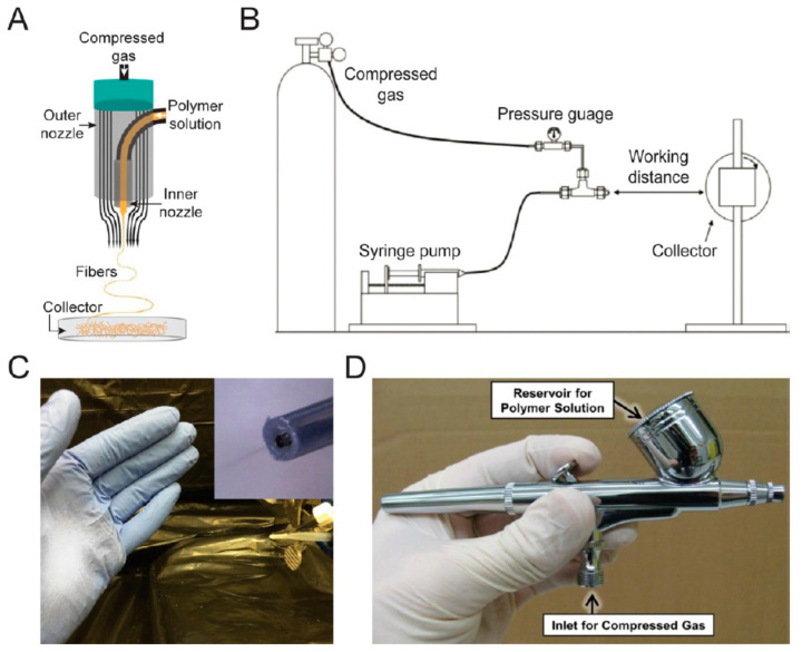
Polyvinylidene fluoride (PVDF)-based piezoelectric materials (PEMs) have found extensive applications in energy harvesting which are being extended consistently to diverse fields requiring strenuous service conditions. Hence, there is a pressing need to mass produce PVDF-based PEMs with the highest possible energy harvesting ability under a given set of conditions. To achieve high yield and efficiency, solution blow spinning (SBS) technique is attracting a lot of interest due to its operational simplicity and high throughput. SBS is arguably still in its infancy when the objective is to mass produce high efficiency PVDF-based PEMs. Therefore, a deeper understanding of the critical parameters regarding design and processing of SBS is essential. The key objective of this review is to critically analyze the key aspects of SBS to produce high efficiency PVDF-based PEMs. As piezoelectric properties of neat PVDF are not intrinsically much significant, various additives are commonly incorporated to enhance its piezoelectricity. Therefore, PVDF-based copolymers and nanocomposites are also included in this review. We discuss both theoretical and experimental results regarding SBS process parameters such as solvents, dissolution methods, feed rate, viscosity, air pressure and velocity, and nozzle design. Morphological features and mechanical properties of PVDF-based nanofibers were also discussed and important applications have been presented. For completeness, key findings from electrospinning were also included. At the end, some insights are given to better direct the efforts in the field of PVDF-based PEMs using SBS technique.

Keywords: (nano)fibers; PVDF; SBS; nanofillers; piezoelectricity.


Conflict of interest statement

The authors declare no conflict of interest.

Figures

Figure 3
Figure 3
(a) Primary polymorphs of PVDF (α, β, γ). (b) Electric field-induced phase transitions of PVDF. The transverse dipole moment of each polymer chain is shown using an orange arrow that points from the negatively charged fluorine atoms to the positively charged hydrogen atoms. T-trans; G-gauche [28].
Figure 4
Figure 4
3D digital microscope observation and infrared microscope scanning of the PVDF samples after being stretched at 100 °C temperature and 1 mms−1 stretching rate. (a) The polarized photo of stretched samples observed by polarized module of 3D Digital Microscope; (b) the corresponding contour chart of F(β) of samples calculated from IR scanning [24].
Figure 5
Figure 5
Various parts of SBS setup [29]: (A) Inlets for polymer solution and air with fibers coming out of nozzle due to attenuation force applied by high speed air [43]. (B) Schematic of SBS setup [44]. (C) Image of direct deposition of poly(styrene-block-isoprene-block-styrene) block copolymer fibers using a homemade solution blow spinning device [43]. (D) Commercial airbrush used for solution blow spinning [45].
Figure 1
Figure 1
(a) Quartz SiO2 and its (b) amorphous crystal structure [2].
Figure 2
Figure 2
Direct and converse piezoelectric effects [4].
Figure 6
Figure 6
Fraction of β-phase obtained with different additives and copolymers [41,46,47,48,49,50,51,52,53,54].
Figure 7
Figure 7
(a) FT-IR spectra and (b) concentration of β-phase at different concentrations of BaTiO3 [46].
Figure 8
Figure 8
Schematic diagram of interaction between positively charged nanoparticles and dipoles in PVDF chains [63].
Figure 9
Figure 9
Various solvent systems used for PVDF-based PEMs and fraction of β-phase obtained [18,27,30,42,46,49,70,78,79,82,83,84,85,86,87,88,89].
Figure 10
Figure 10
SEM images of solution blown thermoplastic polyurethane fibers with different feed rate values produced: (a) 1 mL/h, (b) 10 mL/h, (c) 25 mL/h, (d) 50 mL/h [92].
Figure 11
Figure 11
(a) Velocity contour. (b) Vector field in the vicinity of the nozzle end [100].
Figure 12
Figure 12
Electric field distribution for (a) two-bar collector, and (b) conventional collector [116].
Figure 13
Figure 13
(A) Plot indicating morphology of poly(methyl methacrylate) (PMMA) sprayed using a solution blow spinning (SBS) apparatus at various concentrations and molecular weights. The estimated overlap concentration (c *) is indicated by the dashed line. Scanning electron microscopy (SEM) image of PMMA fibers formed at high molecular weight but below overlap concentration. Scale bar represents 50 μm. (B) SEM images of 50/50 wt. % PMMA/1H,1H,2H,2H-heptadecafluorodecyl polyhedral oligomeric silsesquioxane (PMMA: Mw = 593 kDa, PDI = 2.69) blends sprayed using an SBS apparatus at increasing concentrations of PMMA in solution. Scale bars represent 50, 100, and 50 μm, respectively [29].
Figure 14
Figure 14
Morphology of PVDF-based nanofibers: (a) pristine PVDF, (b) 0.2wt%GO/PVDF, (c) 0.2 wt% graphene/PVDF, (d) 0.2 wt% HNT/PVDF, (e) 0.8 wt% GO/PVDF, (f) 0.8 wt% Gr/PVDF, (g) 0.8 wt% HNT/PVDF, and (h) variation in mean diameter with filler content [98].
Figure 15
Figure 15
(a) Schematic illustration of the piezoelectric response experimental setup and the inset is photograph of the assembled full-fibre sensor; SEM images of (b) PVDF nanofibers, (c) PVDF/nanoclay nanofibers, and (d) PVDF/nanoclay nanofibers by NWS method [26].
Figure 16
Figure 16
(a) Stress-strain curves, and (b) Young’s modulus of the PVDF/BaTiO3 nanocomposites [46].
Figure 17
Figure 17
The structure design of the CPZNs-based self-powered PES. (a) The schematic of the developed smart sensor applied in the field of iHMI. The sketch of the device. (b) Nanofibers film. (c) The photograph of the fabricated sensor under bending mode. (d) Anatomy of sensor. (e) Photo of bent sensor. (f) The SEM image of the nanofibers. (g) The TEM image of a single nanofiber. (h) The result of the FEM simulation. (i) The application of robot hand remote control based on the PES [154].

References

    1. Ikeda T., Ikeda T. Fundamentals of Piezoelectricity. Oxford University Press; Oxford, UK: 1990.
    1. Boussaa S.A., Kheloufi A., Zaourar B., Kerkar F. Valorization of Algerian Sand for Photovoltaic Application. Acta Phys. Pol. A. 2016;129:133–137. doi: 10.12693/APhysPolA.130.133. - DOI
    1. Castro N., Pereira N., Cardoso V.F., Ribeiro C., Lanceros-Mendez S. Micro- and nanostructured piezoelectric polymers: Fundamentals and application. Front. Nanosci. 2019;14:35–65. doi: 10.1016/B978-0-08-102572-7.00002-7. - DOI
    1. Jbaily A., Yeung R.W. Piezoelectric devices for ocean energy: A brief survey. J. Ocean Eng. Mar. Energy. 2015;1:101–118. doi: 10.1007/s40722-014-0008-9. - DOI
    1. Kepler R.G., Anderson R.A. Piezoelectricity in polymers. Crit. Rev. Solid State Mater. Sci. 1980;9:399–447. doi: 10.1080/10408438008243576. - DOI