Review
. 2020 Jun 24;120(12):4969-5004.
doi: 10.1021/acs.chemrev.0c00067. Epub 2020 Jun 15.

Structural Enzymology of Nitrogenase Enzymes

Affiliations
Review

Structural Enzymology of Nitrogenase Enzymes

Oliver Einsle et al. Chem Rev. .

Abstract

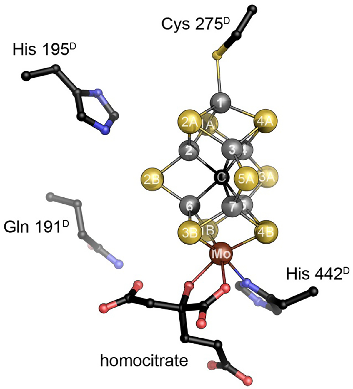
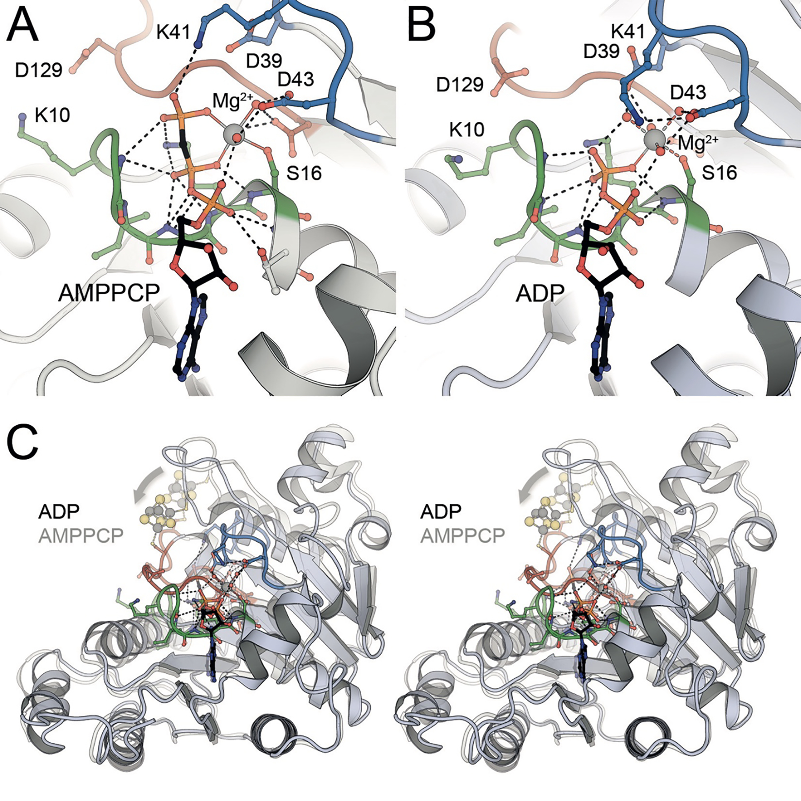
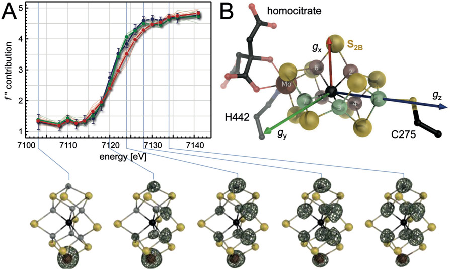
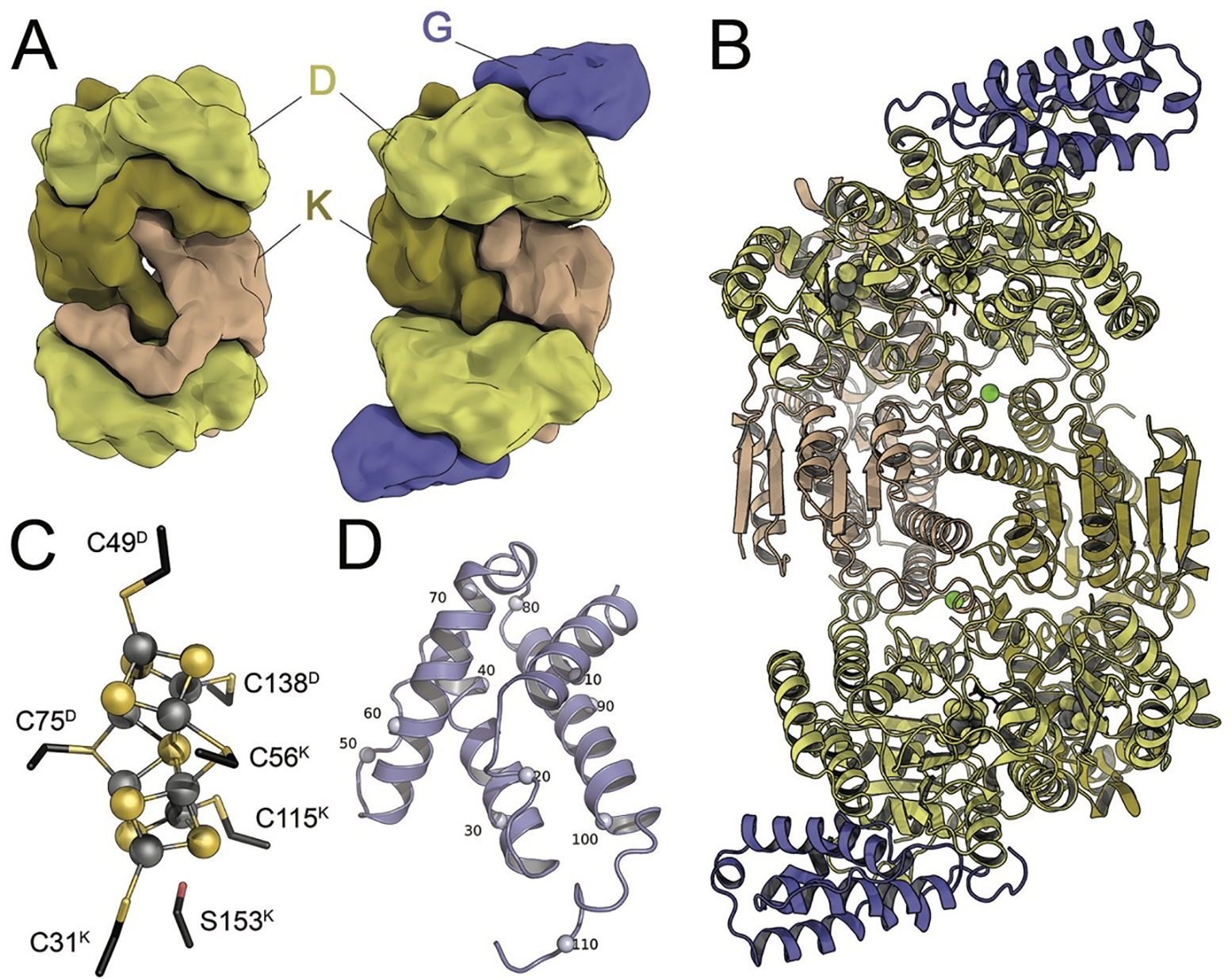
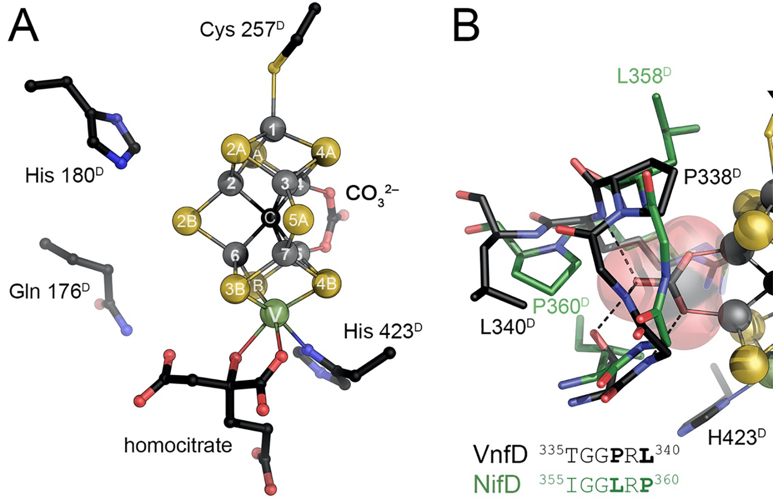
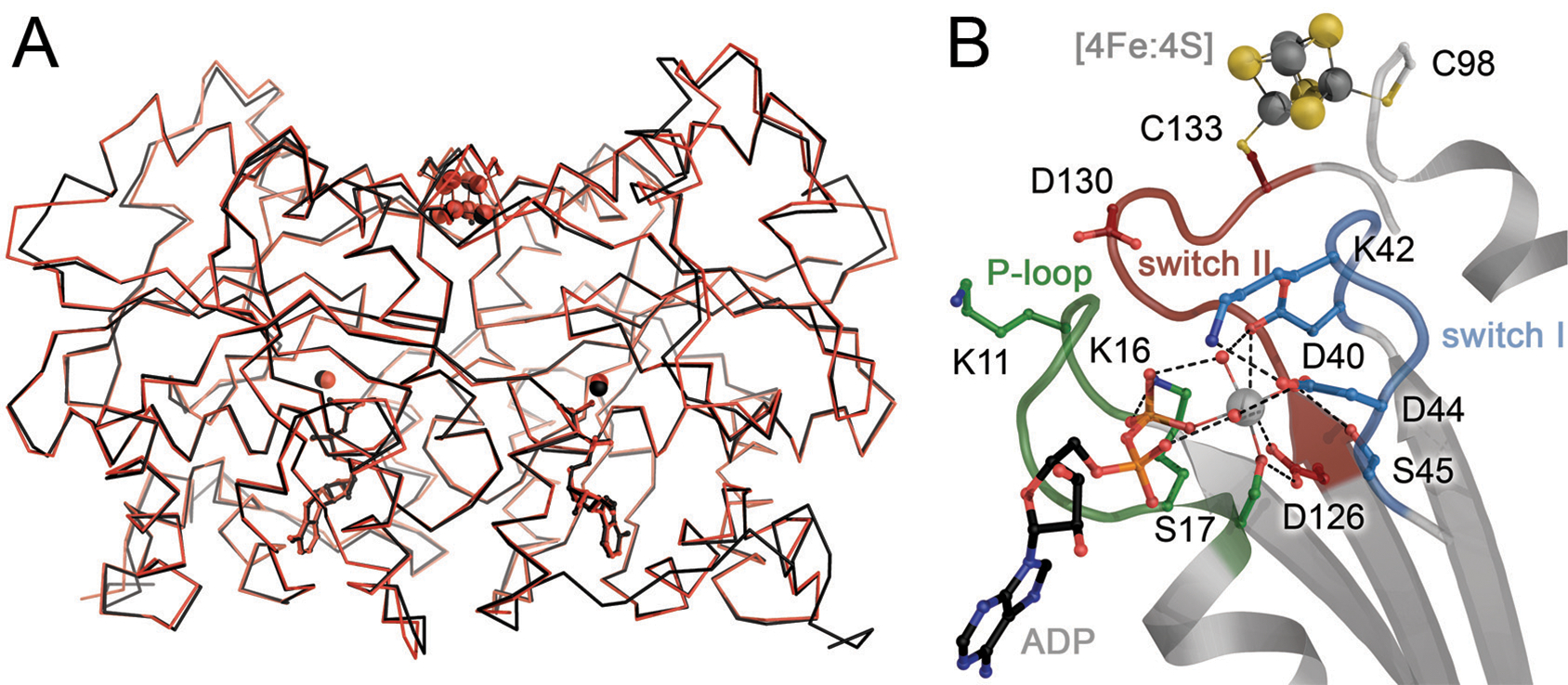
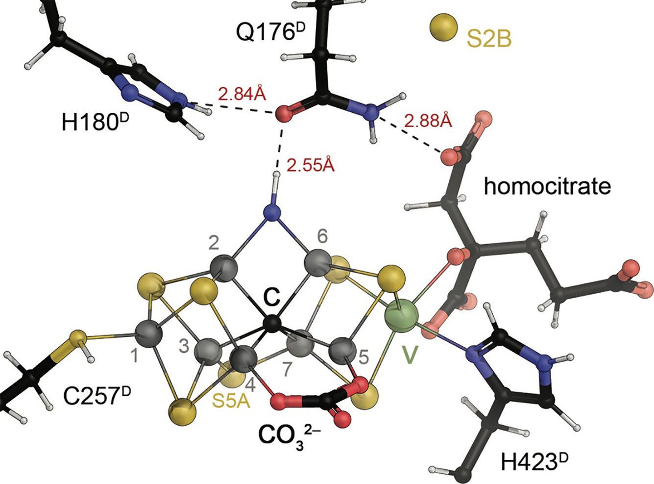
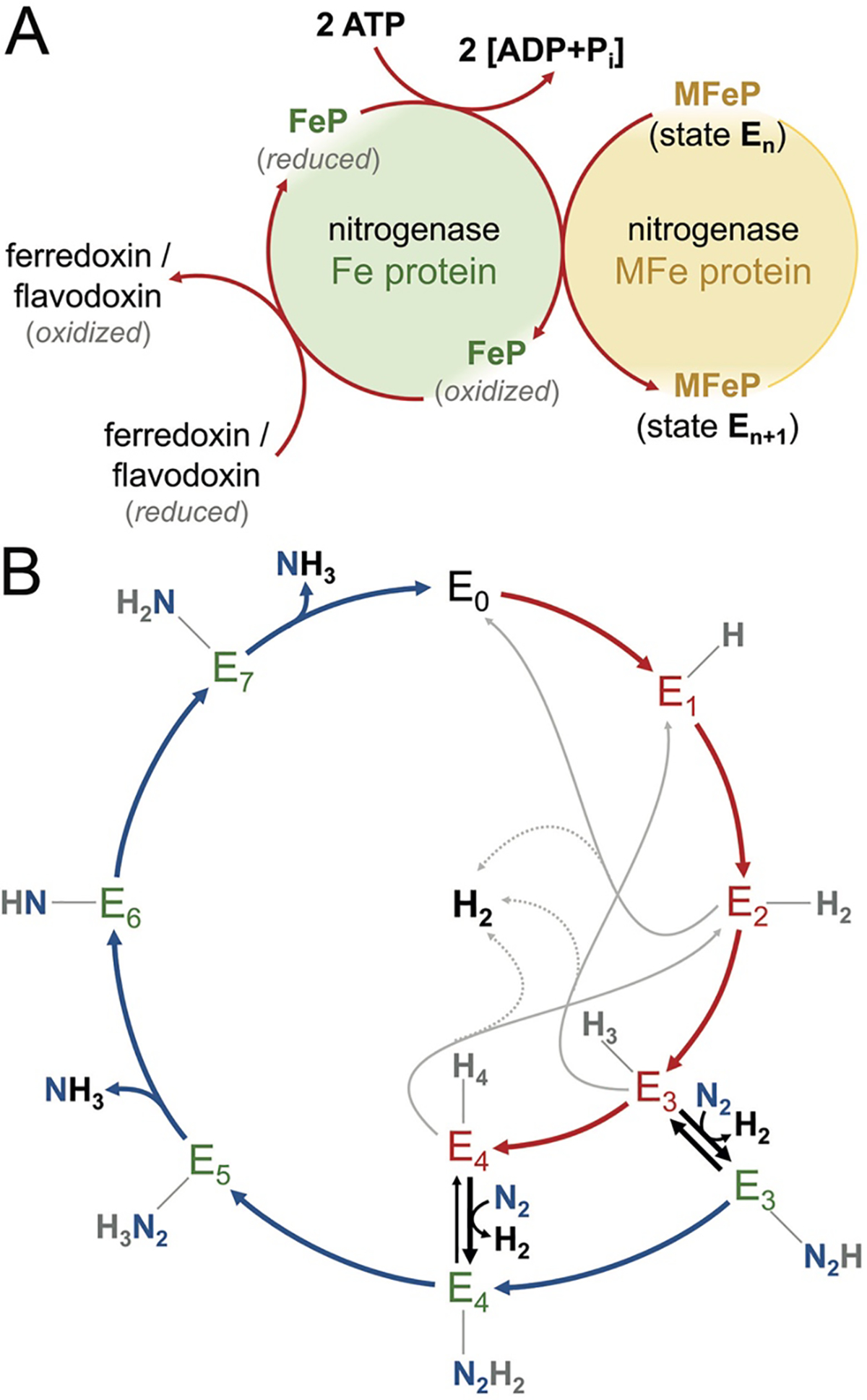
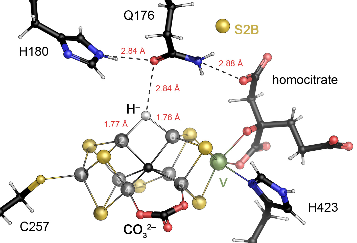
The reduction of dinitrogen to ammonia by nitrogenase reflects a complex choreography involving two component proteins, MgATP and reductant. At center stage of this process resides the active site cofactor, a complex metallocluster organized around a trigonal prismatic arrangement of iron sites surrounding an interstitial carbon. As a consequence of the choreography, electrons and protons are delivered to the active site for transfer to the bound N2. While the detailed mechanism for the substrate reduction remains enigmatic, recent developments highlight the role of hydrides and the privileged role for two irons of the trigonal prism in the binding of exogenous ligands. Outstanding questions concern the precise nature of the intermediates between N2 and NH3, and whether the cofactor undergoes significant rearrangement during turnover; resolution of these issues will require the convergence of biochemistry, structure, spectroscopy, computation, and model chemistry.


Conflict of interest statement

The authors declare no competing financial interest.

Figures

Figure 1:
Figure 1:
Architecture of molybdenum nitrogenase MoFe protein NifDK (PDB 3U7Q). The dinitrogenase component is a NifD2K2 heterotetramer that contains a set of two complex iron-sulfur clusters in each αβ dimer. While the electron-transferring [8Fe:7S] P-cluster is located at the interface of NifD and NifK, the active site FeMo cofactor, a unique [Mo:7Fe:9S:C]:homocitrate moiety, is buried within NifD.
Figure 2:
Figure 2:
The Fe protein of molybdenum nitrogenase. A) The NifH protein forms a homodimer, with each 30 kDa monomer binding ATP or ADP (in stick representation). A conformational change is related to the different ligand-bound states, as Fe protein is a P-loop NTPase. It requires docking to MoFe protein to trigger ATP hydrolysis and electron transfer from its metal site to P-cluster. B) The [4Fe:4S] cluster of Fe protein is coordinated symmetrically at the dimer interface, coordinated by two cysteines from each monomer. Figure generated from PDB 6N4L.
Figure 3:
Figure 3:
The structure of MoFe protein. A) MoFe protein forms an α2β2 heterotetramer in which two αβ units (NifDK) are connected solely via the NifK peptides. Each αβ unit holds a FeMo cofactor and a P-cluster (PDB 3U7Q). B) NifD (above) and NifK (below) are structurally and evolutionarily related and consist of three consecutive Rossmann-fold domains. The domains are highlighted in red, green and blue according to their occurrence in the chain. In NifD, all three domains cradle the FeMo cofactor in their center, while the P-cluster is symmetrically coordinated between the third domains of each chain. C) As typical for this fold, the P-cluster and FeMo cofactor are coordinated at the loop regions at the C-terminus of the parallel β-sheet of a Rossmann domain.
Figure 4:
Figure 4:
A structural comparison of Mo- and V-nitrogenases and their orthologs NifEN and the protochlorophyllide reductase BchNB (DPOR). A) Subunit arrangement of the four orthologs. Coloring scheme as in Fig.1. B) Top view of the complexes, with corresponding coloring of homologous subunits. C) The respective α-subunits of each enzyme in cartoon representation, colored from blue at the N-terminus to red at the C-terminus. Each chain contains three consecutive Rossmann-fold domains (blue, green, red). D) The respective β-subunits in the same orientation as in C). The figure was generated from the PDB entries 3U7Q (NifDK), 5N6Y (VnfDKG), 3PDI (NifEN) and 3AEK (BchNB).
Figure 5:
Figure 5:
Redox-dependent conformational states of P-cluster. A) In the PN state obtained upon reduction with sodium dithionite, the [8Fe:7S]2+ cluster is all-ferrous and symmetrically arranged around a central, six-coordinate sulfide. B) The one-electron-oxidized P1+ state shows a rearrangement of Fe6 only, releasing its interaction with the central sulfide and orienting towards a nearby serine, the largely conserved Ser 188K. C) Two-electron oxidation of the PN state leads to POx, a [8Fe:7S]4+ state in which Fe5, in addition to Fe6, re-orients away from the central sulfide, this time towards a backbone amide. Notably, all observed changes are reversible. D) Redox-dependent structural changes in the [4Fe:3S] cluster of O2-tolerant hydrogenase of C. necator. The shift of Fe4 towards a backbone amide is highly reminiscent of the shift of Fe6 upon oxidation of P-cluster. Panels A)-C) generated from PDB entries 1M1N and 3U7Q, panel D) generated from PDB entry 4IUD.
Figure 6:
Figure 6:
The catalytic FeMo cofactor of Mo nitrogenase. This complex iron-sulfur cluster prominently contains molybdenum at an apical position as a heterometal, bidentally coordinated by a homocitrate molecule. It obtains its highly symmetric structure through the insertion of a central carbide (formally C4−) that originates from S-adenosyl methionine. The [Mo:7Fe:9S:C]:homocitrate cluster is coordinated only by two residues of the NifD subunit, Cys 275 and His 442, and all eight metal ions are coordinatively saturated. Figure made from PDB entry 3U7Q.
Figure 7:
Figure 7:
Nucleotide binding and conformational changes in the Fe protein NifH from A. vinelandii. A) The three phosphate groups of the ATP analog AMPPCP are cradled in the P-loop (green) of the protein, with a bound Mg2+ cation liganded by the β- and γ-phosphate and residues from the switch I (blue) and switch II (red) loops (PDB 4WZB). B) In the ADP-bound state after dissociation of the γ-phosphate, residue K41 from the switch I region (blue) becomes a ligand to Mg2+, leading to a major conformational change (PDB 6N4L). C) In an overlay of the NifH monomers in the AMPPCP- and ADP-bound states, the effect of the conformational change of the switch I (blue) and switch II (red) regions is seen as a displacement of the [4Fe:4S] cluster at the dimer interface (arrow).
Figure 8:
Figure 8:
Nitrogenase complexes. Electron transfer from Fe protein to the catalytic MoFe protein requires the formation of a stoichiometric complex of both components (PDB 1N2C). A) With bound Mg-ADP·AlF4, the [4Fe:4S] of Fe protein is positioned at a distance from P-cluster that is suitable for electron transfer. B) Different nucleotide-bound or -free states of Fe protein bind in different orientations on MoFe protein, but without nucleotide (PDB 2AFH) or with ADP (PDB 2AFI), the distance between the [4Fe:4S] cluster and P-cluster is increased with respect to the form with bound ATP analogs AMPPCP (PDB 4WZB) or ADP·AlF4.
Figure 9:
Figure 9:
Discovery and Identification of the central carbide in FeMo cofactor. A) Calculated, resolution-dependent electron density profiles of the central position of FeMo cofactor, highlighting that the different surrounding atoms (Fe1, Mo, all nine S and the six remaining Fe) have varying effects that sum up to a profile (below) that highlights a negative electron density artifact in the resolution range between 2.2 and 1.55 Å. B) At 1.0 Å resolution, a statistical evaluation of the diffraction behavior of all carbon (black), nitrogen (blue) and oxygen (red) atoms of the structure (PDB 3U7Q), the central light atoms of the two cofactors of the MoFe protein clearly lined up with carbon. C) The result from (B) was corroborated by ESEEM spectroscopy, where only 13C, but not 15N-labelling generated a new signal at the correct Larmor frequency ν. D) Fcalc electron density maps calculated to the stated limiting resolutions underline that the maximum indicating the central carbide indeed disappears at resolutions lower than 1.55 Å, as a direct consequence of the distorting ripple effects of the surrounding atoms as dissected in (A).
Figure 10:
Figure 10:
Analysis of the E0 state of FeMo cofactor by spatially resolved anomalous dispersion (SpReAD). A) In an experiment involving 17 data sets along the K-edge of iron, SpReAD refinement of the 7 individual iron sites of FeMo cofactor revealed the existence of a set of more oxidized Fe sites (Fe2, 4, 5, 6, red average) and a more reduced set (Fe1, 3, 7, green average). The edge position for the latter was very well in line with the all-ferrous P-cluster (blue average). As complementary information, the cofactor structures below show anomalous difference electron density maps for the data sets recorded at the indicated positions along the edge. B) Structure of FeMo cofactor with the more reduced Fe sites in green and the more oxidized ones in red. The axes indicate the principal components of the oriented magnetic g tensor (see Fig. 11A).
Figure 11:
Figure 11:
The electronic structure of the resting state E0 of FeMo cofactor. A) Orientation of the S = 3/2 g tensor of resting-state MoFe protein with respect to the cluster structure from single-crystal EPR analysis. The longest principal component, gz = 4.31, orients along the pseudo-threefold axis of the cofactor. Notably, the gx = 2.01 component is directed towards the Fe2-Fe6 edge that later also proved to be the site of ligand binding. B) Spin-localized model for the S = 3/2 E0 state of MoFe protein. The maximized antiferromagnetic coupling of this model leads to largely localized charges, leaving Fe2 and Fe6 as the most oxidized metal sites in the cluster.
Figure 12:
Figure 12:
Ligand complexes of FeMo cofactor. A) CO complex of A. vinelandii MoFe protein obtained under turnover conditions (PDB 4TKV). The ligand replaced bridging sulfide S2B, but induced no other discernible changes at the active site. B) Under turnover with SeCN, selenide also replaced sulfide S2B (PDB 5BVG). Under continuous turnover, replacement of the other bridging sulfides was also observed, albeit to a lesser degree.
Figure 13:
Figure 13:
The vanadium-iron protein from A. vinelandii. A) Similar to the NifD2K2 heterotetramer (left), the core of VFe protein is a VnfD2K2 assembly with high structural homology to MoFe protein. It additionally contains a further subunit, VnfG, which is in exclusive contact with VnfD. B) Cartoon representation of A. vinelandii VFe protein (PDB 5N6Y). Green spheres denote the bridging Mg2+ ions. C) The P-cluster of VFe protein bridges the D- and K-subunits. In its reduced state it is nearly identical to its MoFe protein counterpart. D) The VnfG subunit forms a four-helix bundle and does not contain additional cofactors. Every tenth residue of VnfG is denoted by a small sphere.
Figure 14:
Figure 14:
The active site FeV cofactor of vanadium nitrogenase. A) FeV cofactor is a [V:7Fe:8S:C:CO32−]:homocitrate cluster with high overall similarity to FeMo cofactor (Fig. 5). A V3+ cation replaces Mo3+, but retains its binding geometry, as well as the organic R-homocitrate ligand (PDB 5N6Y). In addition, FeV cofactor has one μ2-bridging sulfide, S3A, replaced with a μ−1,3-bridging carbonate. B) The carbonate ligand is tightly bound within a loop region of VnfD. In MoFe protein (PDB 3U7Q), the corresponding loop has a single leucine-proline swap due to which the carbonate ligand cannot be accommodated.
Figure 15:
Figure 15:
The Fe protein of V-nitrogenase, VnfH. A) Superposition of NifH (black) and VnfH (red) form A. vinelandii. The two reductases are 91% identical in sequence and can fully complement each other in function. B) The ADP-bound state of VnfH with an octahedrally coordinated Mg2+ cation shows the close spatial proximity of the nucleotide-binding P-loop, the conformationally flexible switch I and II regions and the bridging [4Fe:4S] cluster. Figure made from PDB entry 6Q93.
Figure 16:
Figure 16:
Continuous-wave EPR spectra of nitrogenases. A) X-band spectrum of A. vinelandii MoFe protein in the resting state E0. B) X-band spectrum of the resting state of A. vinelandii VFe protein. C) In the S =3/2 system of the cofactor, the lower Kramer’s doublet dominates the EPR signal. D) In a rhombogram for the lower doublet, both nitrogenases can be described by an axial g-tensor, but differing in rhombicity, with E/D = 0.05 for MoFe and 0.30 for VFe protein.
Figure 17:
Figure 17:
A turnover state structure for A. vinelandii VFe protein. Sulfide S2B that in the resting state E0 bridges Fe ions 2 and 6 relocated by 7 Å to a binding pocket that was created by an inward rearrangement of the sidechain of residue Q176D. It was replaced by a light atom, N or O that must be protonated according to the interatomic distances observed in the 1.2 Å resolution crystal structure. Figure generated from PDB entry 6FEA.
Figure 18:
Figure 18:
The Thorneley-Lowe model for nitrogenase. A) In a Fe protein cycle, the transfer of a single electron obtained from central metabolism via a ferredoxin or flavodoxin requires transient complex formation of the reduced Fe protein with the catalytic component (MFe protein), concomitant with the hydrolysis of 2 ATP/e. As a result, the enzyme is advanced by one E-state in the catalytic cycle. B) The cycle of the MFe protein describes an 8-electron process and consequently cycles through 8 distinct 1-electron steps (E0–E7). An alternating transfer of electrons and protons (or vice versa) is assumed, and notably the binding of the substrate N2 requires the enzyme to be at least in state E3 or E4. From states E1–E4, unproductive H2 evolution is observed, while the exchange of N2 for H2 upon substrate binding is presumed to be a mechanistic requirement.
Figure 19:
Figure 19:
A model for hydride binding to Fe2 and Fe6 in FeV cofactor. Based on the turnover state structure of VFe protein from A. vinelandii, a bridging hydride can be modeled in place of the NH (or OH) ligand observed in the electron density map. Here, the positioning of residue Gln 176 between the likely proton source His 180 and the substrate binding site may be instrumental for the stabilization of the bridging hydride.

References

    1. Guth JH; Burris RH Inhibition of Nitrogenase-Catalyzed NH3 Formation by H2. Biochemistry 1983, 22 (22), 5111. - PubMed
    1. Snider MG; Temple BS; Wolfenden R The path to the transition state in enzyme reactions: a survey of catalytic efficiencies. J. Phys. Org. Chem. 2004, 17 (6–7), 586.
    1. Ingolia NT; Lareau LF; Weissman JS Ribosome Profiling of Mouse Embryonic Stem Cells Reveals the Complexity and Dynamics of Mammalian Proteomes. Cell 2011, 147 (4), 789. - PMC - PubMed
    1. Garcia HG; Tikhonov M; Lin A; Gregor T Quantitative Imaging of Transcription in Living Drosophila Embryos Links Polymerase Activity to Patterning. Curr. Biol. 2013, 23 (21), 2140. - PMC - PubMed
    1. Eady RR Structure-function relationships of alternative nitrogenases. Chem. Rev. 1996, 96 (7), 3013. - PubMed

Publication types