. 2020 Jun 18;20(12):3437.
doi: 10.3390/s20123437.

Proof-of-Principle of a Cherenkov-Tag Detector Prototype

Affiliations

Proof-of-Principle of a Cherenkov-Tag Detector Prototype

Giuseppe Gallo et al. Sensors (Basel). .

Abstract

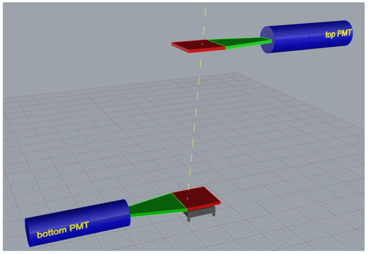
In a recent paper, the authors discussed the feasibility study of an innovative technique based on the directionality of Cherenkov light produced in a transparent material to improve the signal to noise ratio in muon imaging applications. In particular, the method was proposed to help in the correct identification of incoming muons direction. After the first study by means of Monte Carlo simulations with Geant4, the first reduced scale prototype of such a detector was built and tested at the Department of Physics and Astronomy "E. Majorana" of the University of Catania (Italy). The characterization technique is based on muon tracking by means of the prototype in coincidence with two scintillating tiles. The results of this preliminary test confirm the validity of the technique and stressed the importance to enhance the Cherenkov photons production to get a signal well distinguishable with respect to sensors and electronic noise.

Keywords: Cherenkov radiation; VMM3a chip; muography; particle detectors; silicon photo-multiplier.


Conflict of interest statement

The authors declare no conflict of interest.

Figures

Figure 1
Figure 1
Side view of a muon with kinetic energy 102GeV simulated in Geant4. In this simulation, the radiator material is Plexiglass; the size of each tile (biggest horizontal rectangles) is 20×240×240mm3; the external faces are equipped with a regular array of 16×16 silicon photo-multipliers (SiPMs), with size 6×6mm2 (little green rectangles). In the box on the left bottom corner is a front view detail. The yellow dots represent the points at which each Cherenkov (neon green) hits the exit surface of the second radiator.
Figure 2
Figure 2
(a) View of the opened plastic box with the SiPM board on the bottom and filled with optical gel and (b) after the closure with the lid. Board size is 10×10cm2 and the regular array of SiPMs, that are 1.5 cm center-to-center equally spaced, is centered on the board. SiPMs have 6×6mm2 nominal surface area.
Figure 3
Figure 3
2D sketch of the two measurement configurations required to measure muon flux rate detected by the Cherenkov-tag prototype and the corresponding fake events rate. The patterned areas correspond to the optical gel insensitive volume.
Figure 4
Figure 4
Front-End board with VMM3a chip installed.
Figure 5
Figure 5
3D sketch, not to scale, of the experimental setup for the test of Cherenkov-tag prototype. In order to more easily distinguish each component of the trigger system, they are differently colored: Photo-Multiplier tubes (PMTs) are blue, light guides are green and the scintillating tiles are red.
Figure 6
Figure 6
Bar plot of the probability of hitting a certain number of SiPM for the acquisition in UP configuration and SDT = 254. Red and grey bars refers to the probability that n SiPMs are stricken with a measured charge greater than threshold, equal to 70 a.u. in this example.
Figure 7
Figure 7
Comparison between the percentage of correctly tagged events with respect to the number of external triggers and the geometric efficiency calculated with a Monte Carlo simulation (dark yellow horizontal dashed line). This plot refers to values reported in Table 2, with charge threshold equal to 60 a.u. Values reported in the plot near the squared markers correspond to the net rate of correctly-tagged events, i.e., rateUP–rateDOWN in Table 2.
Figure 8
Figure 8
Comparison between the percentage of correctly tagged events with respect to the number of external triggers and the geometric efficiency calculated with a Monte Carlo simulation (dark yellow horizontal dashed line). This plot refers to values reported in Table 4, with charge threshold equal to 70 a.u. Values reported in the plot near the squared markers correspond to the net rate of correctly-tagged events, i.e., rateUP–rateDOWN in Table 4.

References

    1. Tanabashi M., Hagiwara K., Hikasa K., Nakamura K., Sumino Y., Takahashi F., Tanaka J., Agashe K., Aielli G., Amsler C., et al. Review of Particle Physics. Phys. Rev. D. 2018;98:030001. doi: 10.1103/PhysRevD.98.030001. - DOI
    1. Grieder P.K.F. Cosmic Rays at Earth. Elsevier; Amsterdam, The Netherlands: 2001.
    1. Longair M.S. High Energy Astrophysics. Cambridge University Press; Cambridge, UK: 2011.
    1. Nagamine K. Introductory Muon Science. Cambridge University Press; Cambridge, UK: 2003.
    1. George E.P. Cosmic rays measure overburden of tunnel. Commonw. Eng. 1955:455–457.

LinkOut - more resources