. 2020 Jun 19;20(12):3487.
doi: 10.3390/s20123487.

Wireless Power Transfer Techniques for Implantable Medical Devices: A Review

Affiliations

Wireless Power Transfer Techniques for Implantable Medical Devices: A Review

Sadeque Reza Khan et al. Sensors (Basel). .

Abstract

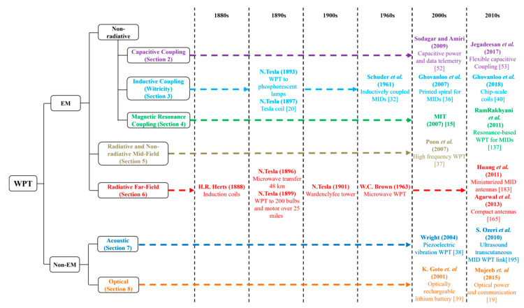
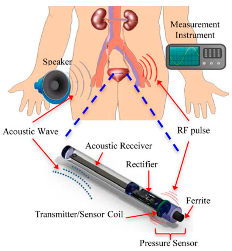
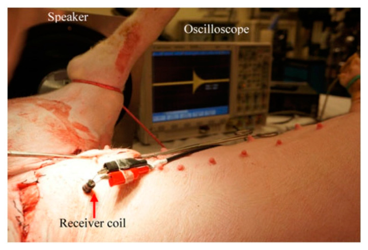
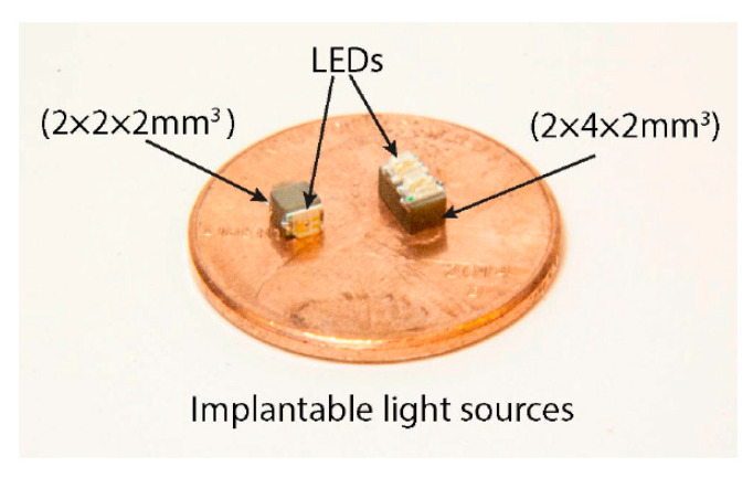
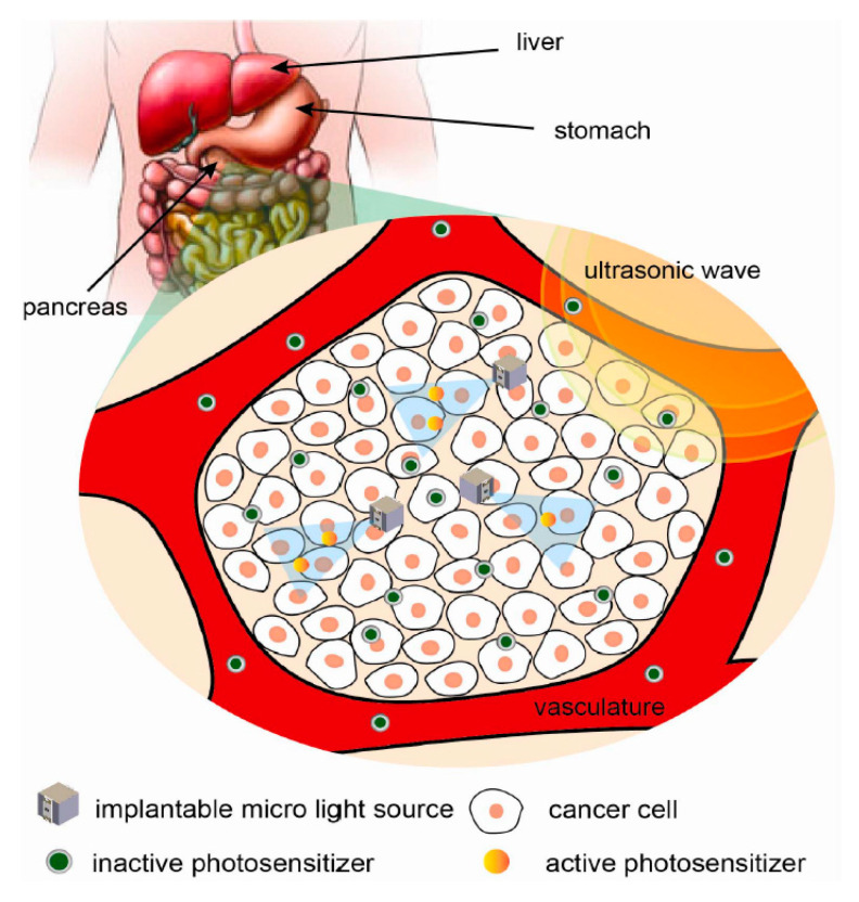
Wireless power transfer (WPT) systems have become increasingly suitable solutions for the electrical powering of advanced multifunctional micro-electronic devices such as those found in current biomedical implants. The design and implementation of high power transfer efficiency WPT systems are, however, challenging. The size of the WPT system, the separation distance between the outside environment and location of the implanted medical device inside the body, the operating frequency and tissue safety due to power dissipation are key parameters to consider in the design of WPT systems. This article provides a systematic review of the wide range of WPT systems that have been investigated over the last two decades to improve overall system performance. The various strategies implemented to transfer wireless power in implantable medical devices (IMDs) were reviewed, which includes capacitive coupling, inductive coupling, magnetic resonance coupling and, more recently, acoustic and optical powering methods. The strengths and limitations of all these techniques are benchmarked against each other and particular emphasis is placed on comparing the implanted receiver size, the WPT distance, power transfer efficiency and tissue safety presented by the resulting systems. Necessary improvements and trends of each WPT techniques are also indicated per specific IMD.

Keywords: acoustic coupling; capacitive coupling; electromagnetic; implantable medical device; optical power transfer; tissue safety; wireless power transfer.


Conflict of interest statement

The authors declare no conflict of interest.

Figures

Figure 1
Figure 1
Classification and research overview of wireless power transfer (WPT) techniques indicating the key milestones relevant to implantable medical devices (IMDs).
Figure 2
Figure 2
Non-radiative capacitive coupling (NRCC) method schematic (taken from [55]. Copyright ©2017, IEEE).
Figure 3
Figure 3
NRCC WPT system [59].
Figure 4
Figure 4
NRIC WPT system powered by alternative electromotive force (EMF). TX: transmitter coil RX; receiving coil.
Figure 5
Figure 5
Optimization flow graph of NRIC WPT system.
Figure 6
Figure 6
Single-ended class-E power amplifier (PA) for NRIC WPT.
Figure 7
Figure 7
Schematic of class-E PA and rectifier system for NRIC.
Figure 8
Figure 8
Geometry of the proposed NRIC WPT link [106]. (a) TX coil printed on FR4 board. (b) RX three-dimensional (3D) antenna embedded in the cerebral spinal fluid (CSF) above the frontal lope of the brain. Copyright © 2018, IEEE.
Figure 9
Figure 9
Measurement of the proposed NRIC WPT link for a piglet [106]. (a) An incision was created in the skull to embed RX coil over the brain. (b) Position of the external TX coil. Copyright © 2018, IEEE.
Figure 10
Figure 10
Proposed two-body packaging for a wireless cortical implant [107]. (a) Components of the package. (b) Fabricated package. Copyright © 2011, IEEE.
Figure 11
Figure 11
Chip-scale RX coils [40]. (a) around-CMOS. (b) above-CMOS. (c) in-CMOS. Copyright © 2018, IEEE.
Figure 12
Figure 12
Different coils and stimulation implant used in the rat experiment [111]. Copyright © 2015, IEEE.
Figure 13
Figure 13
Spinal cord stimulator for StimWave.
Figure 14
Figure 14
Proposed intraocular sensor system for glaucoma treatment [112]. Reproduced with permission from the corresponding author and MDPI Sensors.
Figure 15
Figure 15
Prototype and measurement setup of the proposed system [112]. Reproduced with permission from corresponding author and MDPI Sensors.
Figure 16
Figure 16
Proposed system [113]. External coil is embedded to eyeglasses. A thin and small implantable coil is embedded on a wearable Parylene platform. Reproduced with permission from Springer Nature (Journal: Biomedical Microdevices), Copyright © 2015.
Figure 17
Figure 17
Concept demonstration of eyeglass-powered contact lens [113]. Reproduced with permission from Springer Nature (Journal: Biomedical Microdevices), Copyright © 2015.
Figure 18
Figure 18
ARGUS II retinal prosthesis system [114]. (a) Wearable external parts. (b) Illustration of the implanted parts. Copyright © 2018 Second Sight Medical Products, Inc, USA.
Figure 19
Figure 19
MED-EL cochlear implant NRIC WPT link. Adopted with permission from MED-EL.
Figure 20
Figure 20
Experimental setup of optimized 3D receiver [121]. Copyright © Institute of Physics and Engineering in Medicine. Reproduced with permission of IOP Publishing.
Figure 21
Figure 21
3D WPT system for capsule endoscopy (CE) [122]. (a) Helmholtz TX coil. (b) Structure of the 3D receiver. Reproduced with permission from John Wiley and Sons, Copyright © 2010.
Figure 22
Figure 22
Two-hop NRIC WPT CE system [103]. Copyright © 2012, IEEE.
Figure 23
Figure 23
Non-radiative magnetic resonance coupling (NRMRC) equivalent circuit. (a) Three-coil technique. (b) Four-coil technique.
Figure 24
Figure 24
The three-coil link test setup, including a sheep brain and skull [145]. Copyright © 2017, IEEE.
Figure 25
Figure 25
Eye model for three-coil WPT performance evaluation [146]. Copyright © 2012, IEEE.
Figure 26
Figure 26
Multi-coil WPT retinal prostheses [147]. (a) Possible coil locations. (b) Measurement setup of two-pair coils system. Copyright © 2011, IEEE.
Figure 27
Figure 27
NRMRC WPT system for CE [148]. (a) Designed receiver coil with 9 mm diameter. (b) Experiment setup with a pork chop. Copyright © 2015, IEEE.
Figure 28
Figure 28
NRMRC WPT sub-GHz experimental setup [149]. Reproduced with permission of Electromagnetics Academy.
Figure 29
Figure 29
Complete NRRMF WPT system [158]. The input signal is feed to the TX antenna by a power amplifier following by a matching network. The RX antenna is connected with a matching network, and the output signal is processed through a power regulation circuit.
Figure 30
Figure 30
Current density and magnetic field distribution for a coil source (a,b) and optimal source (c,d) at 2.6 GHz [48,154]. The magnetic field component aligned with the receiver dipole moment and the Poynting vector (white lines) generated by the coil source and the optimal source. Copyright © 2013, IEEE.
Figure 31
Figure 31
RX circuit for NRRMFWPT system.
Figure 32
Figure 32
Wireless cardiac pacing implant [156]. (A) The wireless electrostimulator of 2 mm in diameter. (B) The samedevice before epoxy encapsulation next to a 10-French (~3.3mm) catheter sheath for size comparison. (C) The electrostimulator inserted in the lower epicardium of a rabbit via open-chest surgery. Reproduced with permission of PNAS.
Figure 33
Figure 33
Wireless peripheral nerve neuromodulation system [160]. (a) Conformal wireless powering transmitter. (b) Design of wireless cuff electrodes. (c) Fluoroscopy images of the implanted wireless cuff and transmitter on skin. Copyright © 2017 Tanabe et al.
Figure 34
Figure 34
NRRMF WPT system for CE [161]. (a) Fabricated conformal antenna and 3D capsule prototype. (b) Measurement setup in ASTM phantom. Copyright © 2017, IEEE.
Figure 35
Figure 35
RFF WPT system powered by alternative EMF.
Figure 36
Figure 36
Rectifier schematic for RFF [169]. Copyright © 2014, IEEE.
Figure 37
Figure 37
RX power processing unit for RFF [165].
Figure 38
Figure 38
RFF WPT antenna [183]. (a) Fabricated triple-band miniaturized antenna. (b) Measurement setup embedded in minced pork. Copyright © 2011, IEEE.
Figure 39
Figure 39
Implantable cardiovascular pressure monitoring system [181]. (a) Radiograph of stent implanted in the chest cavity of a live porcine. (b) Optical microscope picture of ASIC including WPT antenna. Copyright © 2010, IEEE.
Figure 40
Figure 40
Typical acoustic power transfer (APT) link.
Figure 41
Figure 41
Representation of near-field and far-field regions of an acoustic wave generated by TX and incident on RX.
Figure 42
Figure 42
Shunt-C class-E amplifier.
Figure 43
Figure 43
Schematic ofthe piezoelectric (PZT) driver.
Figure 44
Figure 44
Proposed implantable micro-oxygen generator (IMOG) device [206]. (a) Conceptual view of IMOG implanted in a pancreatic tumor. (b) Various components in a complete IMOG including ultrasonic power RX. Copyright © 2011, IEEE.
Figure 45
Figure 45
Experimental setup for real-time in vivo oxygen measurement during tumor oxygenation by IMOG [206]. Copyright © 2011, IEEE.
Figure 46
Figure 46
Schematic of APT LC transponder implanted in the bladder [203]. Copyright © 2014, IEEE.
Figure 47
Figure 47
Photograph of in vivo experiment inside pig’s bladder [203].
Figure 48
Figure 48
Mounted micro-light sources on PZT cubes on a US penny. One LED, and two LEDs are mounted on each side of 2 × 2 × 2 mm3 and 2 × 4 × 2 mm3 PZT, respectively [207]. Copyright © 2015, IEEE.
Figure 49
Figure 49
Proposed system showing several implantable micro-light sources to activate the photosensitizer deep inside a tumor powered by ultrasonic wave [207]. Copyright © 2015, IEEE.
Figure 50
Figure 50
Conceptual diagram of the proposed electrical stimulation implant [205]. Copyright © 2018, IEEE.
Figure 51
Figure 51
Complete optical power transfer (OPT) system.
Figure 52
Figure 52
The abstract level figure of the performance of different WPT techniques.

References

    1. Costanzo A., Dionigi M., Masotti D., Mongiardo M., Monti G., Tarricone L., Sorrentino R. Electromagnetic Energy Harvesting and Wireless Power Transmission: A Unified Approach. Proc. IEEE. 2014;102:1692–1711. doi: 10.1109/JPROC.2014.2355261. - DOI
    1. Garnica J., Chinga R.A., Lin J. Wireless Power Transmission: From Far Field to Near Field. Proc. IEEE. 2013;101:1321–1331. doi: 10.1109/JPROC.2013.2251411. - DOI
    1. Wang G., Liu W., Sivaprakasam M., Kendir G.A. Design and analysis of an adaptive transcutaneous power telemetry for biomedical implants. IEEE Trans. Circuits Syst. Regul. Pap. 2005;52:2109–2117. doi: 10.1109/TCSI.2005.852923. - DOI
    1. Sauer C., Stanacevic M., Cauwenberghs G., Thakor N.V. Power harvesting and telemetry in CMOS for implanted devices. IEEE Trans. Circuits Syst. Regul. Pap. 2005;52:2605–2613. doi: 10.1109/TCSI.2005.858183. - DOI
    1. Inanlou F., Ghovanloo M. Wideband Near-Field Data Transmission Using Pulse Harmonic Modulation. IEEE Trans. Circuits Syst. I Regul. Pap. 2010;58:186–195. doi: 10.1109/TCSI.2010.2055351. - DOI

Publication types

LinkOut - more resources