

Mini-LED, Micro-LED and OLED displays: present status and future perspectives
- PMID: 32577221
- PMCID: PMC7303200
- DOI: 10.1038/s41377-020-0341-9
Mini-LED, Micro-LED and OLED displays: present status and future perspectives
Abstract
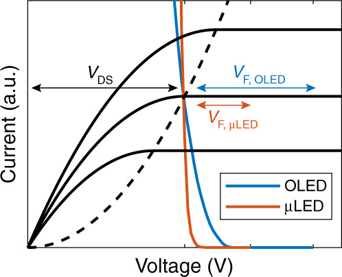
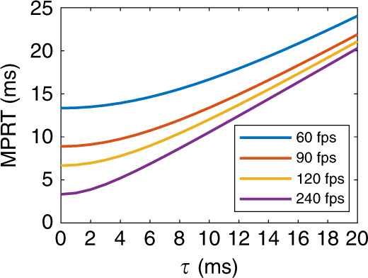
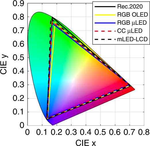
Presently, liquid crystal displays (LCDs) and organic light-emitting diode (OLED) displays are two dominant flat panel display technologies. Recently, inorganic mini-LEDs (mLEDs) and micro-LEDs (μLEDs) have emerged by significantly enhancing the dynamic range of LCDs or as sunlight readable emissive displays. "mLED, OLED, or μLED: who wins?" is a heated debatable question. In this review, we conduct a comprehensive analysis on the material properties, device structures, and performance of mLED/μLED/OLED emissive displays and mLED backlit LCDs. We evaluate the power consumption and ambient contrast ratio of each display in depth and systematically compare the motion picture response time, dynamic range, and adaptability to flexible/transparent displays. The pros and cons of mLED, OLED, and μLED displays are analysed, and their future perspectives are discussed.
Keywords: Displays; Inorganic LEDs.
© The Author(s) 2020.
Conflict of interest statement
Conflict of interestThe authors declare that they have no conflict of interest.
Figures


References
-
- Heilmeier GH, Zanoni LA, Barton LA. Dynamic scattering: a new electrooptic effect in certain classes of nematic liquid crystals. Proc. IEEE. 1968;56:1162–1171.
-
- Schadt M, Helfrich W. Voltage-dependent optical activity of a twisted nematic liquid crystal. Appl. Phys. Lett. 1971;18:127–128.
-
- Schiekel MF, Fahrenschon K. Deformation of nematic liquid crystals with vertical orientation in electrical fields. Appl. Phys. Lett. 1971;19:391–393.
-
- Soref RA. Transverse field effects in nematic liquid crystals. Appl. Phys. Lett. 1973;22:165–166.
-
- Schadt M. Milestone in the history of field-effect liquid crystal displays and materials. Jpn. J. Appl. Phys. 2009;48:03B001.
Publication types
Grants and funding
LinkOut - more resources
Full Text Sources
Other Literature Sources
Miscellaneous
