. 2020 Jun 22;20(12):3530.
doi: 10.3390/s20123530.

Testing System for the Mechanical Properties of Small-Scale Specimens Based on 3D Microscopic Digital Image Correlation

Affiliations

Testing System for the Mechanical Properties of Small-Scale Specimens Based on 3D Microscopic Digital Image Correlation

Xu Liu et al. Sensors (Basel). .

Abstract

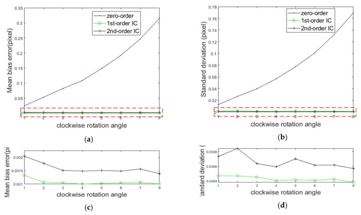
The testing of the mechanical properties of materials on a small scale is difficult because of the small specimen size and the difficulty of measuring the full-field strain. To tackle this problem, a testing system for investigating the mechanical properties of small-scale specimens based on the three-dimensional (3D) microscopic digital image correlation (DIC) combined with a micro tensile machine is proposed. Firstly, the testing system is described in detail, including the design of the micro tensile machine and the 3D microscopic DIC method. Then, the effects of different shape functions on the matching accuracy obtained by the inverse compositional Gauss-Newton (IC-GN) algorithm are investigated and the numerical experiment results verify that the error due to under matched shape functions is far larger than that of overmatched shape functions. The reprojection error is shown to be smaller than before when employing the modified iteratively weighted radial alignment constraint method. Both displacement and uniaxial measurements were performed to demonstrate the 3D microscopic DIC method and the testing system built. The experimental results confirm that the testing system built can accurately measure the full-field strain and mechanical properties of small-scale specimens.

Keywords: camera calibration; digital image correlation; micro tensile machine; shape function; stereo light microscope; undermatching and overmatching.


Conflict of interest statement

The authors declare no conflict of interest.

Figures

Figure 1
Figure 1
Testing system for investigating the mechanical properties of small-scale specimens based on 3D microscopic digital image correlation.
Figure 2
Figure 2
Elements of the micro tensile machine.
Figure 3
Figure 3
Schematic diagram of the light path of a common main objective-stereo light microscope (COM-SLM; ref. [34], Figure 1).
Figure 4
Figure 4
Principle graph of the two-dimensional digital image correlation (2D-DIC) method.
Figure 5
Figure 5
A schematic overview of three-dimensional digital image correlation (3D-DIC).
Figure 6
Figure 6
Speckle image generated by a computer.
Figure 7
Figure 7
Calculated errors of the rigid body translation compared to the set sub-pixel values. (a) Mean bias error and (b) standard deviation.
Figure 8
Figure 8
Calculated errors of the rigid body rotation compared to the set rotation angles. (a) Mean bias error; (b) standard deviation; and (c,d) enlarged views of the red dotted areas in (a) and (b), respectively.
Figure 9
Figure 9
Calculated errors of the uniform deformations compared to the set values. (a) Mean bias error; (b) standard deviation; and (c,d) enlarged views of the red dotted areas in (a) and (b), respectively.
Figure 10
Figure 10
Calculated errors of the non-uniform deformations compared to the set values. (a) Mean bias error; (b) standard deviation.
Figure 11
Figure 11
Sums of squared differences (SSDs) between the reference and current subsets calculated by DIC with three kinds of shape functions: (a) speckle image of rigid translation, (b) speckle image of rigid rotation, (c) speckle image of uniform deformation, and (d) speckle image of non-uniform deformation.
Figure 12
Figure 12
The calibration of a COM-SLM. (a) Calibration device and (b) target (ref. [34], Figure 5 and Figure 6).
Figure 13
Figure 13
In-plane displacement measurement.
Figure 14
Figure 14
Displacements calculated by DIC with two kinds of shape functions with a fixed subset size of 31 pixels × 31 pixels: (a) displacement value and (b) mean bias errors.
Figure 15
Figure 15
Specimen size.
Figure 16
Figure 16
Calculated mean bias errors with different subset sizes using the DIC method by employing three kinds of shape functions.
Figure 17
Figure 17
Images of the in-situ observation of a specimen. (a) Initial state, (b) elastic deformation stage, (c) necking stage, and (d) fracture state.
Figure 18
Figure 18
Real uniaxial tensile experiment of a small-scale specimen. (a) The measured horizontal displacement field and (b) the measured horizontal strain field.
Figure 19
Figure 19
Displacement and load curve of specimens.

References

    1. Pineau A., Benzerga A.A., Pardoen T. Failure of metals III, Fracture and fatigue of nanostructured metallic materials. Acta Mater. 2015;107:508–544. doi: 10.1016/j.actamat.2015.07.049. - DOI
    1. Wu Z.X., Zhang Y.W., Jhon M.H., Gao H.J., Srolovitz D.J. Nanowire Failure: Long = Brittle and Short = Ductile. Nano Lett. 2012;12:910–914. doi: 10.1021/nl203980u. - DOI - PubMed
    1. Keller C., Hug E., Feaugas X. Microstructural size effects on mechanical properties of high purity nickel. Int. J. Plasticity. 2011;27:635–654. doi: 10.1016/j.ijplas.2010.08.002. - DOI
    1. Gianola D.S., Eberl C. Micro- and Nanoscale Tensile Testing of Materials. Jom. 2009;69:24–35. doi: 10.1007/s11837-009-0037-3. - DOI
    1. Johansson S., Fitzpatrick M.E. Errors in crack closure measurements caused by flexure test fixture support effects. Exp. Mech. 2001;41:47–51. doi: 10.1007/BF02323103. - DOI

LinkOut - more resources