. 2020 Jul 21;31(16):1815-1821.
doi: 10.1091/mbc.E20-02-0163. Epub 2020 Jun 17.

Geometry of the nuclear envelope determines its flexural stiffness

Affiliations

Geometry of the nuclear envelope determines its flexural stiffness

Ashutosh Agrawal et al. Mol Biol Cell. .

Abstract

During closed mitosis in fission yeast, growing microtubules push onto the nuclear envelope to deform it, which results in fission into two daughter nuclei. The resistance of the envelope to bending, quantified by the flexural stiffness, helps determine the microtubule-dependent nuclear shape transformations. Computational models of envelope mechanics have assumed values of the flexural stiffness of the envelope based on simple scaling arguments. The validity of these estimates is in doubt, however, owing to the complex structure of the nuclear envelope. Here, we performed computational analysis of the bending of the nuclear envelope under applied force using a model that accounts for envelope geometry. Our calculations show that the effective bending modulus of the nuclear envelope is an order of magnitude larger than a single membrane and approximately five times greater than the nuclear lamina. This large bending modulus is in part due to the 45 nm separation between the two membranes, which supports larger bending moments in the structure. Further, the effective bending modulus is highly sensitive to the geometry of the nuclear envelope, ranging from twofold to an order magnitude larger than the corresponding single membrane. These results suggest that spatial variations in geometry and mechanical environment of the envelope may cause a spatial distribution of flexural stiffness in the same nucleus. Overall, our calculations support the possibility that the nuclear envelope may balance significant mechanical stresses in yeast and in cells from higher organisms.


Figures

FIGURE 1:
FIGURE 1:
Geometry of the nuclear envelope. The outer nuclear membrane (ONM) and the inner nuclear membrane (INM) are fused together at donut-shaped pores with an average diameter of 90 nm. The membranes are maintained at an average separation of 45–50 nm. The spacing between adjacent pores is 250–500 nm.
FIGURE 2:
FIGURE 2:
Calculations of the mechanics of a single-membrane patch. (A) A single membrane of radius 175 nm is subjected to an upward-acting point force at the center. Schematic shows the boundary conditions for the model. At the center (r = 0), the membrane is required to be locally flat and the applied force is equal to F. At the outer boundary (b = 175 nm), the membrane is required to be flat and have zero height. (B) A single membrane with a pore of radius 45 nm (outer radius is 175 nm) is subjected to an upward-acting point force at the inner boundary. Schematic shows the boundary conditions for the model. At the inner boundary (a = 45 nm), the membrane is free to rotate and the applied force is equal to F. At the outer boundary (b = 175 nm), the membrane is required to be flat and have zero height. (C) The cross-section of the membranes under force calculated analytically (solid blue and green lines) and numerically (red and magenta circles) at a maximum displacement of 5 nm. (D) Force-displacement plots calculated from analytical (solid blue and green lines) and numerical calculations (red and magenta circles). The slopes of the lines are ∼0.13 and 0.16 pN/nm for the membranes with no pore and pore, respectively. These are the effective stiffnesses of the two single-membrane systems.
FIGURE 3:
FIGURE 3:
Force application on two membrane patches fused together. (A) Geometry of the nuclear membranes fused at the donut pore under an applied force at the equatorial ring. The schematic shows the geometric quantities and the boundary conditions employed to compute the force-deformation response. The boundary conditions correspond to Eq. 3 in the Methods section. At the inner boundary, the radius is fixed at 45 nm (a = 45 nm) and the total applied force is equal to F. At the outer boundary (b = 175 nm), the two membranes have zero slope with a height equal to half the separation distance between the ONM and INM (H0 = 22.5 nm) below and above the reference plane (z = 0). (B) The system in A is subjected to force at the outer boundary of both the membranes. The total vertical force acting on the two membranes is equal to F. (C) Calculated three-dimensional geometry of the model in A under a force of 7.13 pN and no imposed in-plane tension.
FIGURE 4:
FIGURE 4:
Mechanical response of the two-membrane patch. (A) Force-displacement plots of the two-membrane system depicted in Figure 3A under a prescribed in-plane tension of 0.2 mN/m (purple curve) and zero in-plane tension (yellow curve). The two curves have approximately the same initial slope of 1.65 pN/nm, which is ∼10 times the slope of the single membrane with a pore of 0.16 pN/nm (green curve). (B) The cross-section of the three systems at 5 nm displacement (color coding corresponds to that in A). (C) Force-displacement plots of the two-membrane system depicted in Figure 3B under a prescribed in-plane tension of 0.2 mN/m (purple curve) and zero in-plane tension (yellow curve). The two curves again show an initial slope ∼10 times the slope of the single membrane with a pore (green curve). (D) The cross-section of the three systems at 5 nm displacement (color coding corresponds to that in C).
FIGURE 5:
FIGURE 5:
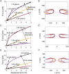
Effect of geometry on the mechanical response of the two-membrane system. (A) Force-displacement plots of the two-membrane system, depicted in Figure 3A, but at bilayer separations of 60 nm (purple curve), 45 nm (yellow curve), and 20 nm (red curve). (B) The calculated geometry of the three systems at a displacement of 5 nm (color coding as in A). (C) Force-displacement plots of the two-membrane system as in Figure 3A, but with outer radii of ∼220 nm (purple curve), 175 nm (yellow curve), and ∼140 nm (red curve). (D) The geometry of the three systems corresponding to a displacement of 5 nm (color coding as in C). (E) Force-displacement plots of the two-membrane system as in Figure 3A, but with pore radii of 67.5 nm (purple curve), 45 nm (yellow curve), and 22.5 nm (red curve). (F) The geometry of the three systems corresponding to a displacement of 5 nm (color coding as in E). The effective flexural stiffnesses at low and high displacements are labeled on the plots in A, C, and E.
FIGURE 6:
FIGURE 6:
Mechanical response of the two-membrane patch at vanishing membrane spacing and pore radius. (A) Force-displacement plot shows a flexural stiffness of 0.3 pN/nm, which is nearly two times the stiffness of a single membrane. (B) The geometry of the membranes corresponding to a displacement of 5 nm.

Comment in

  • Editorial introduction.
    Yap AS. Yap AS. Mol Biol Cell. 2020 Jul 21;31(16):1651-1653. doi: 10.1091/mbc.E20-06-0414. Mol Biol Cell. 2020. PMID: 32692641 Free PMC article.

References

    1. Agrawal A. (2011). Mechanics of membrane– membrane adhesion. Math Mech Solids , 872–886.
    1. Agrawal A, Lele TP. (2019). Mechanicsof nuclear membranes. J Cell Sci , jcs229245. - PMC - PubMed
    1. Agrawal A, Steigmann D. (2009a). Boundary-value problems in the theory of lipid membranes. Continuum Mech Thermodyn , 57–82.
    1. Agrawal A, Steigmann D. (2009b). Modeling protein-mediated morphology in biomembranes. Biomech Model Mechanobiol , 371–379. - PubMed
    1. Belgareh N, Doye V. (1997). Dynamics of nuclear pore distribution in nucleoporin mutant yeast cells. J Cell Biol , 747–759. - PMC - PubMed

Publication types

MeSH terms

Substances

LinkOut - more resources