

Closable Valves and Channels for Polymeric Microfluidic Devices
- PMID: 32605093
- PMCID: PMC7407107
- DOI: 10.3390/mi11070627
Closable Valves and Channels for Polymeric Microfluidic Devices
Abstract
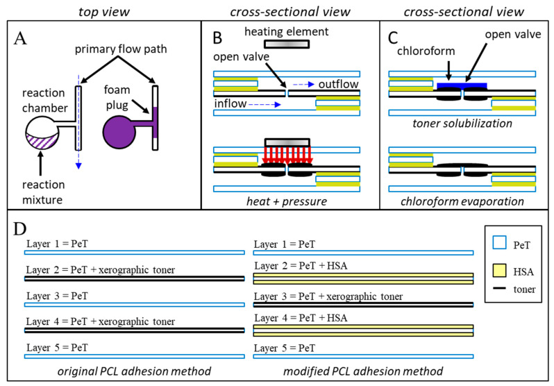
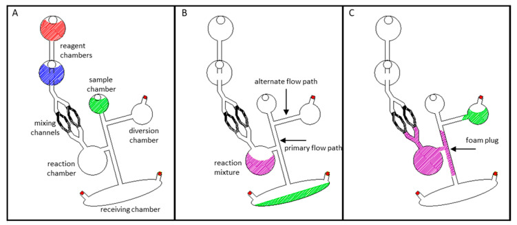
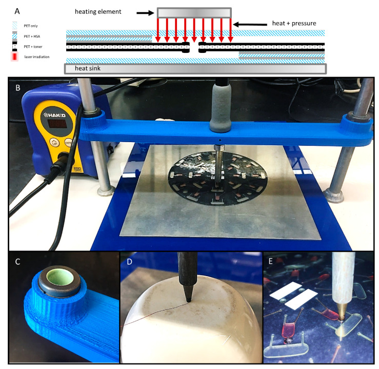
This study explores three unique approaches for closing valves and channels within microfluidic systems, specifically multilayer, centrifugally driven polymeric devices. Precise control over the cessation of liquid movement is achieved through either the introduction of expanding polyurethane foam, the application of direct contact heating, or the redeposition of xerographic toner via chloroform solvation and evaporation. Each of these techniques modifies the substrate of the microdevice in a different way. All three are effective at closing a previously open fluidic pathway after a desired unit operation has taken place, i.e., sample metering, chemical reaction, or analytical measurement. Closing previously open valves and channels imparts stringent fluidic control-preventing backflow, maintaining pressurized chambers within the microdevice, and facilitating sample fractionation without cross-contamination. As such, a variety of microfluidic bioanalytical systems would benefit from the integration of these valving approaches.
Keywords: centrifugal; closable valving; contact heating; expandable foam; microfluidic; redeposition.
Conflict of interest statement
The authors declare no conflict of interest.
Figures
Similar articles
-
Microvalves for Applications in Centrifugal Microfluidics.Sensors (Basel). 2022 Nov 18;22(22):8955. doi: 10.3390/s22228955. Sensors (Basel). 2022. PMID: 36433550 Free PMC article. Review.
-
Optically-controlled closable microvalves for polymeric centrifugal microfluidic devices.Lab Chip. 2020 Apr 21;20(8):1426-1440. doi: 10.1039/c9lc01187k. Epub 2020 Mar 23. Lab Chip. 2020. PMID: 32201873
-
A versatile valving toolkit for automating fluidic operations in paper microfluidic devices.Lab Chip. 2015 Mar 21;15(6):1432-44. doi: 10.1039/c4lc01155d. Lab Chip. 2015. PMID: 25606810 Free PMC article.
-
Capillary Flow-Driven and Magnetically Actuated Multi-Use Wax Valves for Controlled Sealing and Releasing of Fluids on Centrifugal Microfluidic Platforms.Micromachines (Basel). 2022 Feb 16;13(2):303. doi: 10.3390/mi13020303. Micromachines (Basel). 2022. PMID: 35208427 Free PMC article.
-
Centrifugal microfluidic platforms: advanced unit operations and applications.Chem Soc Rev. 2015 Oct 7;44(17):6187-229. doi: 10.1039/c4cs00371c. Epub 2015 Jun 2. Chem Soc Rev. 2015. PMID: 26035697 Review.
Cited by
-
Low-High-Low Rotationally Pulse-Actuated Serial Dissolvable Film Valves Applied to Solid Phase Extraction and LAMP Isothermal Amplification for Plant Pathogen Detection on a Lab-on-a-Disc.ACS Omega. 2024 Jan 9;9(3):3262-3275. doi: 10.1021/acsomega.3c05117. eCollection 2024 Jan 23. ACS Omega. 2024. PMID: 38284094 Free PMC article.
-
Microvalves for Applications in Centrifugal Microfluidics.Sensors (Basel). 2022 Nov 18;22(22):8955. doi: 10.3390/s22228955. Sensors (Basel). 2022. PMID: 36433550 Free PMC article. Review.
-
Revolutionizing the female reproductive system research using microfluidic chip platform.J Nanobiotechnology. 2023 Dec 19;21(1):490. doi: 10.1186/s12951-023-02258-7. J Nanobiotechnology. 2023. PMID: 38111049 Free PMC article. Review.
-
Digital process control of multi-step assays on centrifugal platforms using high-low-high rotational-pulse triggered valving.PLoS One. 2023 Sep 8;18(9):e0291165. doi: 10.1371/journal.pone.0291165. eCollection 2023. PLoS One. 2023. PMID: 37682949 Free PMC article.
References
-
- Glière A., Delattre C. Modeling and fabrication of capillary stop valves for planar microfluidic systems. Sens. Actuators A Phys. 2006;130:601–608. doi: 10.1016/j.sna.2005.12.011. - DOI
LinkOut - more resources
Full Text Sources
Other Literature Sources
Research Materials
