

Design of custom-made navigational template of femoral head and pilot research in total hip resurfacing arthroplasty
- PMID: 32605554
- PMCID: PMC7325234
- DOI: 10.1186/s12893-020-00807-7
Design of custom-made navigational template of femoral head and pilot research in total hip resurfacing arthroplasty
Abstract
Background: To develop a novel custom-made navigational template for accurate prosthesis implantation in total hip resurfacing arthroplasty (THRA) by computer-aided technology.
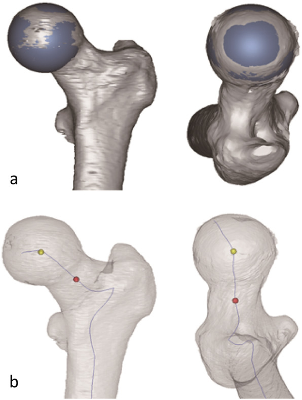
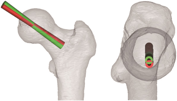
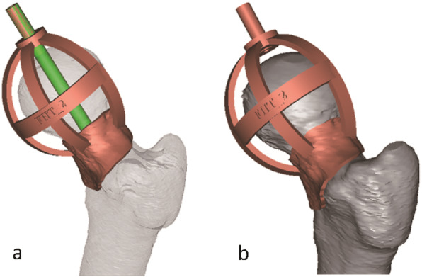
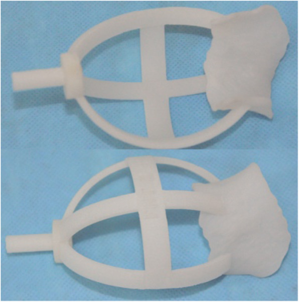
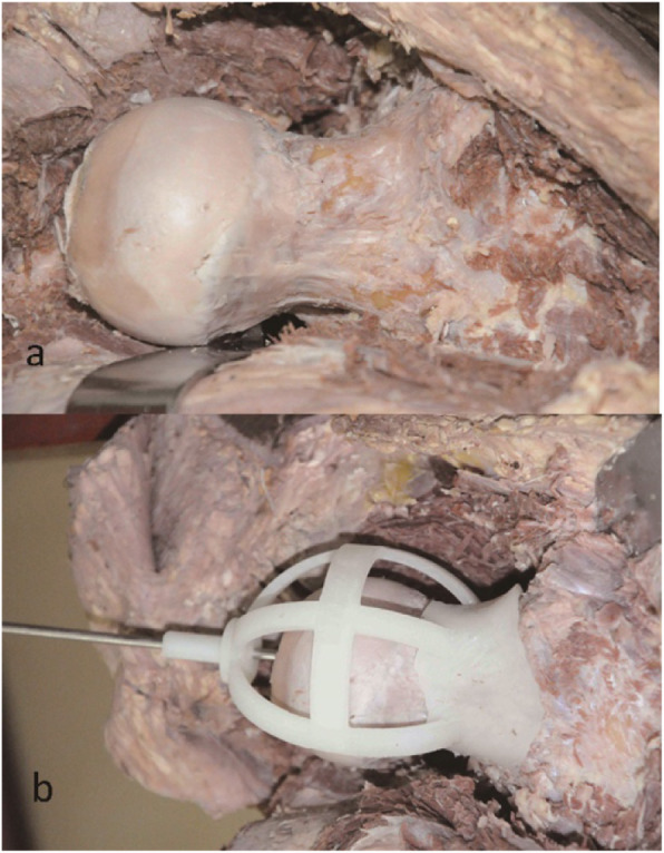
Methods: The template was produced based on data preoperatively acquired from computed tomography (CT) scan. The position of the drill guide was obtained according to the anatomical axis of the femoral neck which was defined by the point of the femoral head center and another point of the femoral neck center. The final direction of the drill guide was confirmed by a valgus angle. The surface of the template was constructed based on the inverse of the femoral neck surface. Then the template was made of acrylate resin by using rapid prototyping (RP) technique. Finally, all the templates were verified in 17 cadavers arranged for THRA and postoperative medical images were employed to evaluate the accuracy and validity of the template.
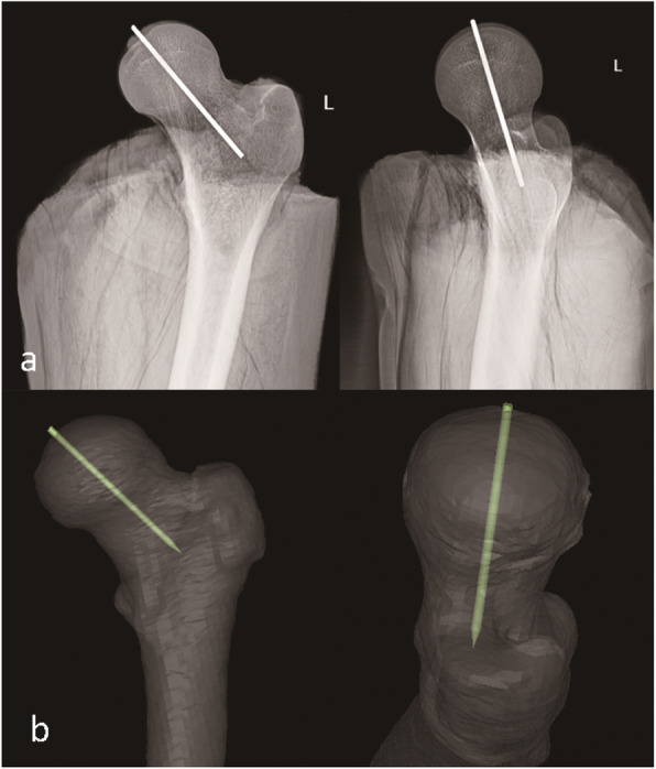
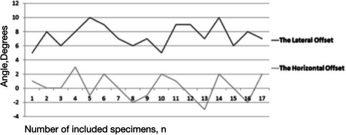
Results: The templates had achieved a high fitting with the femoral neck surface, and there were no guide failures. Postoperative evaluation revealed that the Kirschner-wires pass through the center of the femoral head and femoral neck, presenting a relative expected and acceptable valgus angle to the central axis of the femoral neck. The lateral offset showed the relative valgus angle achieved as expected, the horizontal offset showed that no obvious antero-posterior deviation occured. The comparison between the preoperative Neck-shaft angle (NSA) and the postoperative Stem-shaft angle (SSA) showed there is no significant difference(P > 0.05).
Conclusion: The novel custom-made navigational template of femoral head can effectively assist surgeons for accurately implanting the femoral head components to the desired position in THRA.
Keywords: Anatomical axis of the femoral neck; Computer assisted surgery; Custom-made navigational template; Rapid prototyping; Total hip resurfacing Arthroplasty.
Conflict of interest statement
The authors declared no potential conflicts of interest with respect to the research, authorship, and/or publication of this article.
Figures

Similar articles
-
A custom-made guide-wire positioning device for hip surface replacement arthroplasty: description and first results.BMC Musculoskelet Disord. 2010 Jul 14;11:161. doi: 10.1186/1471-2474-11-161. BMC Musculoskelet Disord. 2010. PMID: 20630093 Free PMC article. Clinical Trial.
-
Femoral Morphology in the Dysplastic Hip: Three-dimensional Characterizations With CT.Clin Orthop Relat Res. 2017 Apr;475(4):1045-1054. doi: 10.1007/s11999-016-5119-2. Clin Orthop Relat Res. 2017. PMID: 27752989 Free PMC article.
-
Femoral offset: anatomical concept, definition, assessment, implications for preoperative templating and hip arthroplasty.Orthop Traumatol Surg Res. 2009 May;95(3):210-9. doi: 10.1016/j.otsr.2009.03.010. Epub 2009 May 6. Orthop Traumatol Surg Res. 2009. PMID: 19423418 Review.
-
Improved implantation technique for resurfacing arthroplasty of the hip.Oper Orthop Traumatol. 2006 Sep;18(3):214-24. doi: 10.1007/s00064-006-1172-4. Oper Orthop Traumatol. 2006. PMID: 16953347 Clinical Trial. English, German.
-
The influence of the size of the component on the outcome of resurfacing arthroplasty of the hip: a review of the literature.J Bone Joint Surg Br. 2010 Apr;92(4):469-76. doi: 10.1302/0301-620X.92B4.22967. J Bone Joint Surg Br. 2010. PMID: 20357319 Review.
Cited by
-
Feasibility and anteversion accuracy of a patient-specific instrument for femoral prosthesis implantation in total hip arthroplasty.Biomed Eng Online. 2023 Sep 13;22(1):90. doi: 10.1186/s12938-023-01152-5. Biomed Eng Online. 2023. PMID: 37705017 Free PMC article.
-
A novel three-dimensional evaluation protocol to assess the consistency of critical screw angles between preoperative planning and 3d-printed patient-specific acetabular revision prostheses.Front Bioeng Biotechnol. 2025 Aug 18;13:1604285. doi: 10.3389/fbioe.2025.1604285. eCollection 2025. Front Bioeng Biotechnol. 2025. PMID: 40901254 Free PMC article.
-
Imaging in Hip Arthroplasty Management-Part 1: Templating: Past, Present and Future.J Clin Med. 2022 Sep 16;11(18):5465. doi: 10.3390/jcm11185465. J Clin Med. 2022. PMID: 36143112 Free PMC article. Review.
-
Three-dimensionally printed navigational template: a promising guiding approach for lung biopsy.Transl Lung Cancer Res. 2022 Mar;11(3):393-403. doi: 10.21037/tlcr-22-172. Transl Lung Cancer Res. 2022. PMID: 35399565 Free PMC article.
-
Clinical applications and prospects of 3D printing guide templates in orthopaedics.J Orthop Translat. 2022 May 13;34:22-41. doi: 10.1016/j.jot.2022.03.001. eCollection 2022 May. J Orthop Translat. 2022. PMID: 35615638 Free PMC article. Review.
References
MeSH terms
Grants and funding
LinkOut - more resources
Full Text Sources
Medical
Research Materials
