Review
. 2021 May;40(3):280-305.
doi: 10.1002/mas.21642. Epub 2020 Jul 1.

THE IMS PARADOX: A PERSPECTIVE ON STRUCTURAL ION MOBILITY-MASS SPECTROMETRY

Affiliations
Review

THE IMS PARADOX: A PERSPECTIVE ON STRUCTURAL ION MOBILITY-MASS SPECTROMETRY

Jacob W McCabe et al. Mass Spectrom Rev. 2021 May.

Abstract

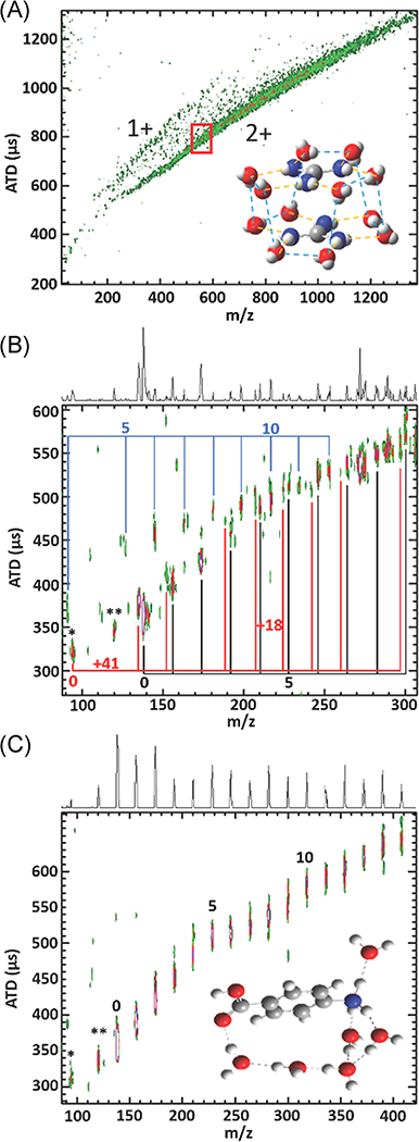
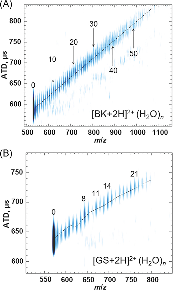
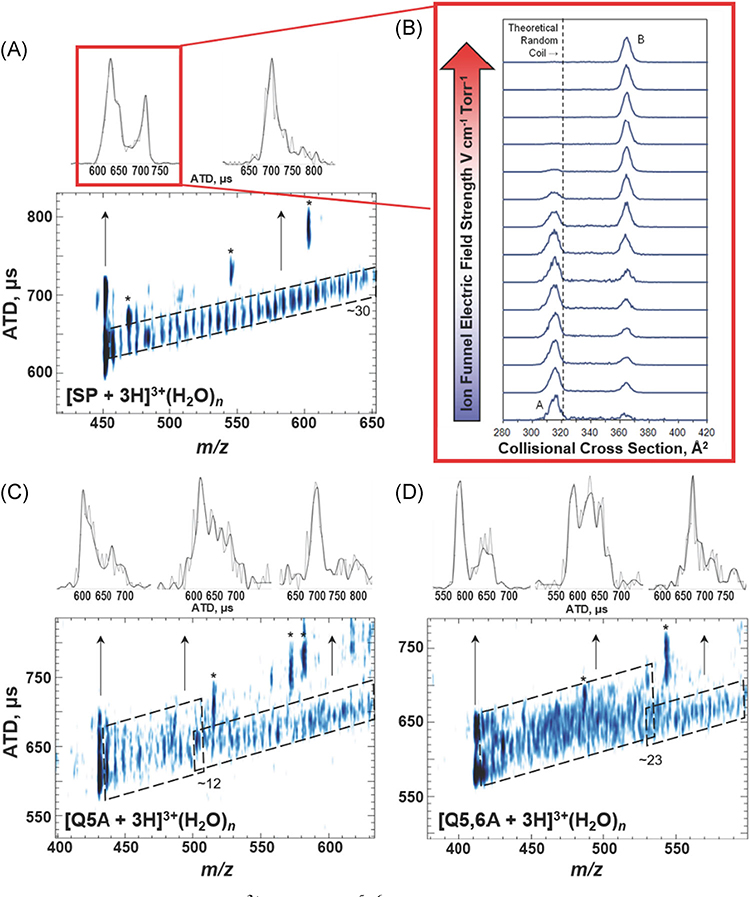
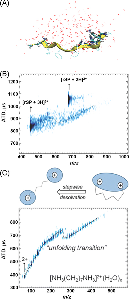
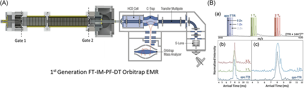
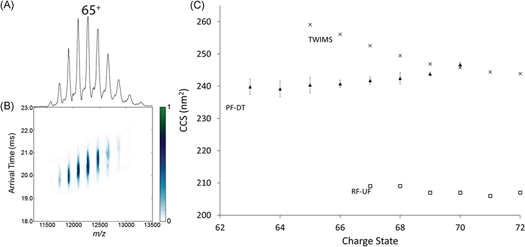
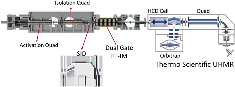
Studies of large proteins, protein complexes, and membrane protein complexes pose new challenges, most notably the need for increased ion mobility (IM) and mass spectrometry (MS) resolution. This review covers evolutionary developments in IM-MS in the authors' and key collaborators' laboratories with specific focus on developments that enhance the utility of IM-MS for structural analysis. IM-MS measurements are performed on gas phase ions, thus "structural IM-MS" appears paradoxical-do gas phase ions retain their solution phase structure? There is growing evidence to support the notion that solution phase structure(s) can be retained by the gas phase ions. It should not go unnoticed that we use "structures" in this statement because an important feature of IM-MS is the ability to deal with conformationally heterogeneous systems, thus providing a direct measure of conformational entropy. The extension of this work to large proteins and protein complexes has motivated our development of Fourier-transform IM-MS instruments, a strategy first described by Hill and coworkers in 1985 (Anal Chem, 1985, 57, pp. 402-406) that has proved to be a game-changer in our quest to merge drift tube (DT) and ion mobility and the high mass resolution orbitrap MS instruments. DT-IMS is the only method that allows first-principles determinations of rotationally averaged collision cross sections (CSS), which is essential for studies of biomolecules where the conformational diversities of the molecule precludes the use of CCS calibration approaches. The Fourier transform-IM-orbitrap instrument described here also incorporates the full suite of native MS/IM-MS capabilities that are currently employed in the most advanced native MS/IM-MS instruments. © 2020 John Wiley & Sons Ltd. Mass Spec Rev.

Keywords: 1st principles CCS; conformational heterogeneity; cryogenic ion-mobility MS; drift tube ion mobility; native MS/IM-MS; orbitrap MS.


Figures

FIGURE 1.
FIGURE 1.
Comparison of native IM-MS to other the more conventional structural biology techniques used for structural studies. First presented by M. L. Gross as part of 2018 Symposium to honor his ACS Award in Analytical Chemistry. IM, ion mobility; MS, mass spectrometry.
FIGURE 2.
FIGURE 2.
(A) 2-D plots of mobility (arrival-time distributions or CCS) vs m/z illustrating of separation on the basis of compound class and “conformation space.” (B) Mobility (ATD) vs m/z plots for the hemoglobin tryptic peptide fragment ions (residues 104–115, LLGNVLVVVLAR (m/z 1275.5) and residues 30–39, LLVVYPWTQR m/z 1284.5). Reproduced from McLean et al. (2005) and Ruotolo et al. (2002a). ATD, arrival time distributions; CCS, collision cross section.
FIGURE 3.
FIGURE 3.
Solvent-dependent CCS profiles and examples of four low-energy structures for bradykinin 3+ ions in solution phase and “dehydrated” states. The solvent composition used for each solvent system is shown to the right of each plot. Reproduced from Pierson et al., 2011. CCS, collision cross section.
FIGURE 4.
FIGURE 4.
A qualitative folding landscape for PPI/PPII transitions for Pro13 in vacuo. system. The barrier height is estimated from collision voltages rather than more accurate solution phase measurements or well-defined single collision energies. Note that the reaction D→C varies with H2O and is highest for a “dry” environment. Adapted from Shi et al. (2016b).
FIGURE 5.
FIGURE 5.
Solidworks rendering of (A) the cryo-IM-MS source and (B) instrument with major components labeled. Ions generated by electrospray ionization are transferred to the heated capillary (red), which is heated to control the degree of hydration. Ions are then passed through the DC ion guide (green) and into the cryogenic IM drift tube (light blue). The kinetically trapped, hydrated ions are preserved as they pass through the drift tube by using drift gas precooled by liquid nitrogen circulating through the Dewar jacket (dark blue). After leaving the drift tube, the ions are detected by TOF mass analyzer. Instrument details are described in further detail elsewhere (Silveira et al., 2013b). TOF, time-of-flight.
FIGURE 6.
FIGURE 6.
(A) ATD is plotted as a function of m/z for a mixture of GdmH+(H2O)n (denoted 1+) with GdmH+(H2O)n and GdmH+-GdmH+(H2O)n (denoted 2+). The red box highlights where the ion abundance begins to decrease with decreasing hydration numbers. The inset shows a proposed structure of GdmH+-GdmH+(H2O)12. (B) ATD vs m/z plot of 4-ABAH+(H2O)n sprayed from 0.1% formic acid in H2O showing the change in the trendline at the n = 6 proton transfer from –NH3+ to –COHOH+. (C) ATD vs m/z plot of a mixture of H+(H2O)n, 4-ABAH+(H2O)n, and NH3 +C6H5(ACN)1(H2O)n clusters labelled in blue, black, and red, respectively, sprayed from 0.1% formic acid in 1:1 ACN/H2O. This plot shows no clear change in the trendline suggesting the –COHOH+ conformer persists. *denotes 94 m/z (CO2 loss) and **denotes 120 m/z (H2O loss). Adapted from Hebert and Russell (2019) and Hebert and Russell (2020). ATD, arrival time distribution.
FIGURE 7.
FIGURE 7.
Cryo-IM-MS plots of (A) bradykinin peptide and (B) gramicidin S. BK displays a typical example of the linear desolvation patterns of larger molecules, whereas GS shows distinct shifts in the mobility and magic number clusters. Adapted from Servage et al. (2016) and Silveira et al. (2013b). BK, bradykinin; Cryo-IM-MS, cryogenic ion mobility-mass spectrometry; GS, gramicidin S.
FIGURE 8.
FIGURE 8.
(A) ATD vs m/z for SP3+ ions (RPKPQ5Q6FFGLM). (B) Plot of CCS as a function of the electric field strength of two [SP + 3H]3+ conformers CCS, illustrating the conversion of species A to B under collision induced unfolding conditions. The theoretical random coil trendline (321 Å2) is shown with a dashed line. (C) and ATD vs m/z for SP mutant Q5A and (D) Q5,6A. All peaks labeled with an asterisk correspond to fragment ions observed at higher capillary temperatures. The upper panels contain extracted ATD for specific m/z ranges as indicated by the arrows. The black ATD lines are the result of plotting every other data point while the full data set is plotted in gray. Note that the differences in the peak widths of the extracted ATDs reveal conformational heterogeneity for the ions at each m/z ratio. While the plots of ATD vs m/z were collected using an 80 K drift tube, the plot of ion funnel electric field strength versus CCS was collected under ambient conditions. Adapted from Servage et al. (2015a) and Silveira et al. (2013b). ATD, arrival time distributions; CCS, collision cross section.
FIGURE 9.
FIGURE 9.
(A) MDS of hydrated rSP. (B) m/z vs ATD plot of rSP showing the conformational change undergone by increased desolvation. MDS of solvated rSP ion (C) m/z vs ATD plot of 1,7-diammoniumheptane demonstrates the impact water has on structure on solvated ions, with inset schematic of changes in solvation motif with dehydration. Adapted from Kim et al. (2017); Servage et al. (2015a). ATD, arrival time distributions; rSP, retro-sequence substance P.
FIGURE 10.
FIGURE 10.
(A, B) Plots of the evolution of two fully elongated structures showing the (raw data, black line; smoothed, yellow line) CCS of SP3+ ions and (blue points) numbers of water molecules vs time extracted from selected simulations. The experimentally determined CCS of SP3+ (316 Å2 orange dash and 368 Å2, green dash) is also shown for reference. Structures labeled as (i−iii) depict representative snapshots of the simulations (A, B): (i) the post-fission compact structures observed at 2000 ps, (ii) the elongated structures observed later in the simulation, and (iii) the final frame of the desolvation simulation. Blue dots represent water molecules, purple spheres represent Cl, and H3O+ are shown in green. Figure is from Kim et al. (2017). CCS, collision cross section.
FIGURE 11.
FIGURE 11.
(A–C) Heat maps showing the effect of collisional activation on the CCS profiles of [M + nH + xCl](nx)+ ubiquitin ions, with a total charge of 5+, 6+, and 7+ (A–C, respectively). The CCS profiles observed using a collision voltage of 5 V is shown to the left of each map. Adapted from Wagner et al. (2016). CCS, collision cross section.
FIGURE 12.
FIGURE 12.
ATD vs m/z plot for ubiquitin at heated capillary temperatures of (A) 363 K and (B) 378 K, and (C) an annotated structure of the native state of ubiquitin. The hydrophobic patch (orange) and surrounding basic (blue), acidic (red), and glutamine (purple) residues are shown. The hydrophobic patch (L8, I44, V70) is surrounded by K6, K11 (not visible), R42, K48, H68, R72, and R74 residues, which are more solvent accessible and may serve as initiators of dimer formation. Adapted from Servage et al. (2015b).
FIGURE 13.
FIGURE 13.
CIU heatmaps of ubiquitin dimers [2M + 9H]9+ from acidified solutions (0.1% formic acid). (A) NMR structure of K48-linked ubiquitin dimer (PDB 2PEA). (B) CIU of the noncovalent ubiquitin dimer shows unfolding from a from ~1,750 A2 to ~2,300 A2 before dissociation at a collision voltage of 25 V. CIU heatmaps of (C) K6-, (D) K11-, (E) K48-, and (F) K63-linked covalent ubiquitin dimers show similar conformer distributions at low collision voltages yet distinct linkage-dependent unfolding. Similarities between the unfolding pathways of noncovalent and K48-linked ubiquitin dimers (B and E, respectively) suggest the noncovalent dimer adopts similar subunit interfacial interactions to the K48-linked covalent ubiquitin dimer. CIU heatmaps are reproduced from references Wagner and Russell (2016); Wagner et al. (2017). CIU, collision-induced unfolding; NMR, nuclear magnetic resonance.
FIGURE 14.
FIGURE 14.
The average charge state (z¯) for ubiquitin (10 μM in acetic acid, pH 3.0) was determined from the spectra shown in the upper left by taking the weighted average of charge state as function of solution temperature. The midpoint at Tm = 71°C is in excellent agreement with 71 ± 2°C reported by Wintrode et al. (1994). Reproduced from El-Baba et al. (2017).
FIGURE 15.
FIGURE 15.
(A) CCS distributions for [M + 9H]9+-[M + 13H]13+ions of ubiquitin at various temperatures. Traces are shown in different colors when IMS peaks for different charge states show indistinguishable temperature profiles. (B) Relative abundance profiles as a function of temperature for each configuration reveal three distinct solution products (P1, P2, P3) and one high-temperature equilibrium intermediate (I2). Relative abundances of these identified conformers show distinct freezing curves as these conformers form from the unfolding/refolding of the compact, native ubiquitin ions at elevated temperatures. Reproduced from El-Baba et al. (2017). CCS, collision-induced unfolding.
FIGURE 16.
FIGURE 16.
(A) Melting curves for myohemerythrin (20 μM in 30 mM ammonium acetate, pH 6.8) show a unique unfolding and refolding pathway dictated by a structural rearrangement and formation of a non-native disulfide bond. Inset mass spectra show shifts towards higher charge and transition from holoprotein (filled circles) to apoprotein (open circles) with increasing temperature, followed by a shift towards lower charge state following the formation of the nonnative disulfide bond at high temperature. (B) Structures of the products formed by melting are shown along with respective CCS profiles and MS spectra. Reproduced from Woodall et al. (2019).
FIGURE 17.
FIGURE 17.
CIU and melting data for WT-, CT-, and FT2-TTR. CIU heatmaps of (A) WT, (B) C-terminal tagged (CT), and (C) dual flag tagged (FT2) show that FT2 tag increases gas- and solution-phase stability of TTR and alters its unfolding pathway in the gas phase as a third intermediate was observed in CIU plot. (D) Solution stability was measured using I50 values corresponding to the energy required to dissociate 50 percent of the tetramer. T4 was used as a control as it is known that it enhances the solution stability of TTR. (E) I50 values for WT-, CT-, and FT2-TTR were plotted as a function of temperature, demonstrating slightly higher stability of FT2-TTR at room temperature which diminishes at higher temperatures. Reproduced from Shirzadeh et al. (2020). CIU, collision-induced unfolding; TTR, transthyretin; WT, wild-type.
FIGURE 18.
FIGURE 18.
(A) Solidworks schematic of first generation FT-IM-PF-DT coupled to a Thermo Scientific Exactive Plus orbitrap MS with EMR that was used for the following section of experimentation Briefly, ion is generated via static-spray nano-ESI into a heated capillary at ~100°C. Ions are then transmitted into an RF ion funnel at (250 Vpp). The ion beam is modulated at both the Gate 1 and Gate 2 by a linear frequency chirp of 5–5,005 Hz over 8 min to overcome the duty-cycle mismatch of IM separation and MS analysis. (B) Resolved peaks for T4 and endogenous zinc binding to TTR and corresponding ATDs obtained from instrument shown in panel A. Figure is adapted from Poltash et al. (2018). ATD, arrival time distributions; DT, drift-tube; EMR, extended mass range; ESI, electrospray ionization; FT, Fourier-transform; IM, ion-mobility; PF, periodic-focusing; TTR, transthyretin.
FIGURE 19.
FIGURE 19.
(A) Stepwise increase in the mass of TTR upon electrospray ionization. (B) ATDs of TTR14+ (a) just loaded and (b) after 20 hr continuous ESI showing the unfolding of TTR due to oxidation (multiple extended conformers shown with green and purple peaks). (C) Repeated experiment as panel (A) but using Synapt G2 (Waters) without sufficient resolving power to detect stepwise 64 Da mass shift on tetramer, and (D) corresponding SID spectra showing ejected monomers. (E) SID spectra for M4+ showing several oxidations on monomeric TTR as well as zinc binding. Reproduced from Poltash et al. (2019). ESI, electrospray ionization; SID, surface-induced dissociation; TTR, transthyretin.
FIGURE 20.
FIGURE 20.
SID dissects topology of TTR products of SUE and provides a detailed mechanism of TTR disassembly in solution. (A) SID of 2:2 heterotetramer consisting of light/light and heavy/heavy dimers yields a mass spectrum for two homodimers with equal ion abundance. (B) For SID of an equimolar mixture of 2:2 heterotetramers, a ratio of 1:4:1 (LL/LH/HH) is obtained for dimers. (C) TTR disassembly mechanism supported by SID of SUE exchange products. After mixing the reactants, dissociation to dimers results in the production of the first product, shown in purple box and panel (A). Following dissociation of dimers to monomers yields all three topologies of 2:2 heterotetramer at equilibrium, shown in green box and panel (B). Reproduced from Shirzadeh et al. (2019). HH, light/light; LL, heavy/heavy; SUE, subunit exchange; TTR, transthyretin.
FIGURE 21.
FIGURE 21.
(A) Mass spectra, (B) ATD vs m/z plots, and (C) CCS vs CSD of native GroEL (810 kDa) with comparisons to PF-DT, TWIMS, RF-UF in 200 mM ammonium acetate. ATD, arrival time distributions; CCS, collision cross section; RF-UF, radio-frequency confining uniform field; PF-DT, periodic focusing drift tube; TWIMS, traveling-wave ion mobility.
FIGURE 22.
FIGURE 22.
Solidworks schematic of the implementation of a modular qQ-SID platform with FT-IM-PF-DT on the UHMR platform. The design of the SID cell is similar to that described by Zhou and Wysocki (2014). SID, surface-induced dissociation; UHRM, ultra-high mass resolution.

References

    1. Allen SJ, Bush MF. 2016. Radio-frequency (Rf) confinement in ion mobility spectrometry: Apparent mobilities and effective temperatures. J Am Soc Mass Spectrom 27(12):2054–2063. - PubMed
    1. Allison TM, Reading E, Liko I, Baldwin AJ, Laganowsky A, Robinson CV. 2015. Quantifying the stabilizing effects of protein-ligand interactions in the gas phase. Nat Commun 6:8551. - PMC - PubMed
    1. Benesch JL, Sobott F, Robinson CV. 2003. Thermal dissociation of multimeric protein complexes by using nanoelectrospray mass spectrometry. Anal Chem 75(10):2208–2214. - PubMed
    1. Benesch JLP. 2009. Collisional activation of protein complexes: Picking up the pieces. J Am Soc Mass Spectrom 20(3):341–348. - PubMed
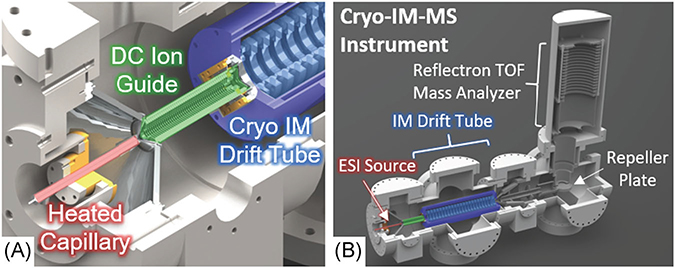
    1. Blase RC, Silveira JA, Gillig KJ, Gamage CM, Russell DH. 2011. Increased ion transmission in IMS: A high resolution, periodic-focusing DC ion guide ion mobility spectrometer. Int J Mass Spectrom 301(1-3):166–173.

Publication types

LinkOut - more resources