

Design and capital cost optimisation of three-phase gravity separators
- PMID: 32613098
- PMCID: PMC7321976
- DOI: 10.1016/j.heliyon.2020.e04065
Design and capital cost optimisation of three-phase gravity separators
Abstract
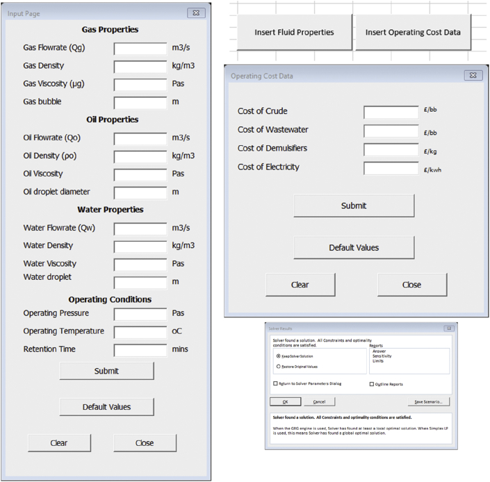
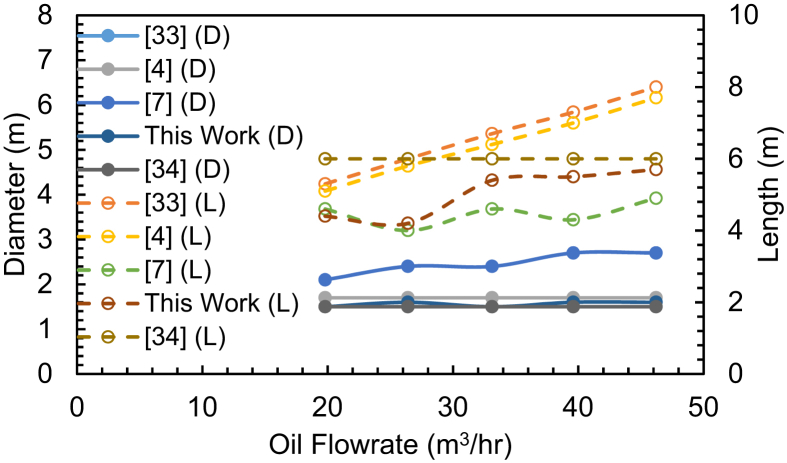
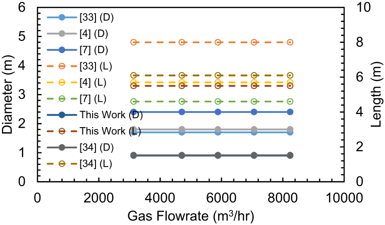
The separation of produced fluids is essential once it reaches the surface. This separation is achieved in gravity separators. The design and sizing of separators can be challenging due to the number of factors involved. Improper separator design can bottleneck and reduce the production of the entire facility. This paper describes the development of a capital cost optimisation model for sizing three phase separators. The developed model uses GRG Non-linear algorithms to determine the minimum cost associated with the construction of horizontal separators subject to four sets of constraints. A numerical sizing example was solved to provide the details associated with the model and the ease with which parameters can be varied to suit the user's needs. Finally, a spreadsheet comparison between results obtained from the developed model and four other extant models is carried out. Results indicated that the developed model predicted results within an absolute error of ±5m3 in most cases and a maximum of ±12.5m3 for very high gas flows in comparison to conventional models developed based on retention time theory.
Keywords: Capital cost; Chemical engineering; Mathematical modeling; Mathematical optimisation; Oil and gas; Organic chemistry; Petroleum engineering; Petroleum industry; Three phase separator.
© 2020 The Authors.
Figures


References
-
- IEA. Organisation for Economic Co-operation and Development; OECD: 2017. World Energy Outlook 2017.
-
- Vileiniskis M., Remenyte-Prescott R., Rama D., Andrews J. Fault detection and diagnostics of a three-phase separator. J. Loss Prev. Process. Ind. 2016;41:215–230.
-
- Song J.H., Jeong B.E., Kim H.J., Gil S.S. Offshore Technology Conference. 2010. Three-phases separator sizing using drop size distribution.
-
- Arnold K., Stewart M. In: Chapter 5 - Three-phase Oil and Water Separation. Arnold ” K., Stewart M., editors. Gulf Professional Publishing; Burlington: 2008. pp. 244–315.
-
- Ghaffarkhah A., Shahrabi M.A., Moraveji M.K. 3D computational-fluid-dynamics modeling of horizontal three-phase separators: an approach for estimating the optimal dimensions. SPE Prod. Oper. 2018;33(04):879–895.
Publication types
LinkOut - more resources
Full Text Sources
