. 2020 Jul 14;20(14):3915.
doi: 10.3390/s20143915.

Interleaved Array Transducer with Polarization Inversion Technique to Implement Ultrasound Tissue Harmonic Imaging

Affiliations

Interleaved Array Transducer with Polarization Inversion Technique to Implement Ultrasound Tissue Harmonic Imaging

Chan Yuk Park et al. Sensors (Basel). .

Abstract

In ultrasound tissue harmonic imaging (THI), it is preferred that the bandwidth of the array transducer covers at least the fundamental frequency f0 for transmission and the second harmonic frequency 2f0 for reception. However, it is challenging to develop an array transducer with a broad bandwidth due to the single resonance characteristics of piezoelectric materials. In this study, we present an improved interleaved array transducer suitable for THI and a dedicated transducer fabrication scheme. The proposed array transducer has a novel structure in which conventional elements exhibiting f0 resonant frequency and polarization-inverted elements exhibiting 2f0 resonant frequency are alternately located, and the thicknesses of all piezoelectric elements are identical. The performance of the proposed method was demonstrated by finite element analysis (FEA) simulations and experiments using a fabricated prototype array transducer. Using the proposed technique, f0 and 2f0 frequency ultrasounds can be efficiently transmitted and received, respectively, resulting in a 90% broad bandwidth feature of the transducer. Thus, the proposed technique can be one of the potential ways to implement high resolution THI.

Keywords: finite element analysis (FEA) simulation; interdigital bonding process; interleaved array transducer; polarization inversion technique; tissue harmonic imaging.


Conflict of interest statement

The authors declare no conflict of interest.

Figures

Figure 1
Figure 1
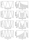
Operational principle of the conventional and polarization inversion technique (PIT) models: (a) Conventional structure with a single piezoelectric layer, (b) polarization-inverted layer structure with a 0.25 inversion ratio (front-side inversion model), (c) polarization-inverted layer structure with a 0.25 inversion ratio (back-side inversion model), and (d) the PIT with a 0.5 inversion ratio (half-inversion model). Note that the time and frequency responses of the radiated ultrasound waves at interface A for each case were also demonstrated by computational simulation, as shown in Figure 2.
Figure 2
Figure 2
Time and frequency responses of the radiated ultrasound waves at interface A for each case in Figure 1 based on MATLAB simulations: (a) Time and (b) frequency domain responses of the conventional model, (c) time and (d) frequency domain responses of the PIT with a 0.25 inversion ratio (front-side inversion model), (e) time and (f) frequency domain responses of the PIT with a 0.25 inversion ratio (back-side inversion model), and (g) time domain and (h) frequency domain responses of the PIT with a 0.5 inversion ratio (half inversion model).
Figure 3
Figure 3
FEA-based schematic diagram of the proposed array transducer using the PIT for tissue harmonic imaging (THI). The array transducer was composed of the conventional elements for transmitting f0 ultrasounds and the PIT elements for receiving reflected 2f0 ultrasounds. The conventional elements exhibited the same poling direction, but the PIT elements exhibited the opposite poling direction. The identical matching layers were applied to the proposed model.
Figure 4
Figure 4
FEA simulated electrical impedance (solid line: magnitude; dashed line: phase) and pulse–echo response (solid line: frequency-domain spectrum; dashed line: time-domain waveform) of the proposed linear array transducer with matching layers: (a) Electrical impedance of the conventional element, (b) electrical impedance of the PIT element, (c) pulse–echo response of the conventional element, and (d) pulse–echo response of the PIT element.
Figure 5
Figure 5
Fabrication process of the proposed prototype array transducer. The improved interleaved technique was employed for this fabrication.
Figure 6
Figure 6
Fabrication process of the proposed prototype array transducer focusing on the novel interleaved technique.
Figure 7
Figure 7
Photographs of the prototype array transducer: (a) Prototype array transducer after bonding matching and backing layers, (b) magnified photograph of a red-dotted circle in (a) before bonding matching layers (top view), and (c) magnified photograph of (b) before the sub-dicing process (cross sectional side view).
Figure 8
Figure 8
Experimental setup for pulse–echo measurement. Two pulsers/receivers were used for independent pulse–echo test of each element and the test for transmitting f0 and receiving reflected 2f0 frequency components: (a) Schematic diagram and (b) photograph of (a).
Figure 9
Figure 9
Measured electrical impedance (solid line: magnitude; dashed line: phase) and pulse–echo responses (solid line: frequency-domain spectrum; dashed line: time-domain waveform) of the proposed linear array transducer with matching layers: (a) Electrical impedance of the conventional element, (b) electrical impedance of the PIT element, (c) pulse–echo response of the conventional element, and (d) pulse–echo response of the PIT element.
Figure 10
Figure 10
Measured pulse–echo response of the proposed linear array transducer when the f0 element Table 2. f0 element receives the reflected ultrasounds: (solid line: frequency-domain spectrum; dashed line: time-domain waveform).

References

    1. Hedrick W.R., Metzger L. Tissue harmonic imaging: A review. J. Diagn. Med. Sonogr. 2005;21:183–189. doi: 10.1177/8756479305276477. - DOI
    1. Averkiou M.A., Roundhill D.N., Powers J.E. A new imaging technique based on the nonlinear properties of tissues; Proceedings of the IEEE Ultrasonic Symposium; Toronto, ON, Canada. 5–8 October 1997; pp. 1561–1566.
    1. Song J.H., Kim S.W., Sohn H.Y., Yoo Y.M. Coded excitation for ultrasound tissue harmonic imaging. Ultrasonics. 2010;50:613–619. doi: 10.1016/j.ultras.2010.01.001. - DOI - PubMed
    1. Duck F.A. Nonlinear acoustics in diagnostic ultrasound. Ultrasound Med. Biol. 2002;28:1–18. doi: 10.1016/S0301-5629(01)00463-X. - DOI - PubMed
    1. Burns P.N., Simpson D.H., Averkiou M.A. Nonlinear imaging. Ultrasound Med. Biol. 2000;26:S19–S22. doi: 10.1016/S0301-5629(00)00155-1. - DOI - PubMed

LinkOut - more resources