. 2021 Jan 1;32(1):012002.
doi: 10.1088/1361-6528/aba70f.

Roadmap on emerging hardware and technology for machine learning

Affiliations

Roadmap on emerging hardware and technology for machine learning

Karl Berggren et al. Nanotechnology. .

Abstract

Recent progress in artificial intelligence is largely attributed to the rapid development of machine learning, especially in the algorithm and neural network models. However, it is the performance of the hardware, in particular the energy efficiency of a computing system that sets the fundamental limit of the capability of machine learning. Data-centric computing requires a revolution in hardware systems, since traditional digital computers based on transistors and the von Neumann architecture were not purposely designed for neuromorphic computing. A hardware platform based on emerging devices and new architecture is the hope for future computing with dramatically improved throughput and energy efficiency. Building such a system, nevertheless, faces a number of challenges, ranging from materials selection, device optimization, circuit fabrication and system integration, to name a few. The aim of this Roadmap is to present a snapshot of emerging hardware technologies that are potentially beneficial for machine learning, providing the Nanotechnology readers with a perspective of challenges and opportunities in this burgeoning field.


Figures

Figure 1.
Figure 1.
(a) Generic scheme of analog vector-by-matrix multiplication in a crossbar circuit with adjustable crosspoint devices. For clarity, the output signal is shown for just one column of the array. (b-d) Schematic cross-sections of (b) synaptic transistor, and (c) ESF1 and (d) ESF3 supercells. ESF stands for Embedded SuperFlash NOR flash memory technology. Such technology is based on array of supercells, with each supercell hosting two split-gate floating-gate transistors. (e) 2×2 fragment of the ESF1 supercell array, highlighting the routing of word lines in the original NOR flash memory (dashed green lines) and in the array modified for analog applications (solid green lines). (f) Network for classification of MNIST benchmark images, with 105+ FG cells, implemented in 180-nm technology, and (g) the typical dynamics of the network’s input signal, the output of a sample hidden-layer neuron, and all network’s outputs, after an abrupt turn-on of the voltage shifter’s power supply [6].
Figure 2.
Figure 2.
(a) 3D NAND flash memory circuit consisting of vertical strings of NAND cells. Here, a time-domain VMM operation may be performed simultaneously with all cells of one x-y layer, selected by applying a smaller voltage to a specific word plane, while keeping all other word planes biased with larger “pass” voltage. (b) Time-domain vector-by-matrix multiplication scheme, and (c) its timing diagram. On panel (b), the adjustable current sources describe the FG cells of a particular layer, while the inputs are pulse-duration-encoded enable signals applied to the select transistors that connect each 3D NAND string to a bit line. (d) Comparison of general-purpose neuromorphic accelerators, evaluated on inference tasks of comparable complexity, at similar functional accuracy [10].
Figure 1.
Figure 1.
Variants of switching mechanisms used for emerging non-volatile memories. a) In ferroelectric switching the dipoles of a ferroelectric material are switched by an electrical field. b) In a magnetic tunnel junction the magnetization of a free layer is switched between the parallel and anti-parallel orientation towards a fixed reference layer. c) In phase change memories the phase of a chalcogenide is switched between amorphous and crystalline using joule heating and (d) in ion movement based memories a conductive filament made of metal atoms or oxygen vacancies is reversibly formed and ruptured.
Figure 2.
Figure 2.
SET (red curves) and RESET (green curves) of a switch for use in a synapse for SNN or a weight device for ANN. Ideal characteristics for the usage as weight is added in blue.
Figure 1.
Figure 1.
Working principles of phase change memory (PCM) and resistive RAM (RRAM) devices. Fig. 1a shows a cell, the active PCM area is in between a top and bottom electrode, including a heater to induce melt/quench cycles. As heat is applied the active channel will change its conductivity based on the phase of the channel. Reproduced with permission [4] Copyright 2010, IEEE. Fig. 1b shows a typical filamentary RRAM, as a writing current is applied to the cell, free ions move together to form a connection between the top and bottom electrodes. Reproduced with permission [1] Copyright 2019, John Wiley and Sons.
Figure 2.
Figure 2.
(a) Schematics of a crossbar array. (b) Thermal crosstalk due to Joule heating in adjacent cells. Adapted with permission [3], Copyright 2015 Nature Publishing Group.
Figure 1.
Figure 1.
Roadmap of heterogenous integration of emerging device arrays
Figure 1.
Figure 1.
Tentative roadmap for crossbar density, along with logic and memory device scaling, according to the International Roadmap for Devices and Systems.
Figure 2.
Figure 2.
Strategies for memristor crossbar arrays fabrication and integration with underlying CMOS devices.
Figure 1.
Figure 1.
Defectivity ranges, tolerances, and mitigation actions for different operational modes. Defectivity ranges are approximate and sensitive to degree of redundancy, network design (for networks) and the precise technology and fabrication routes (for device technologies).
Figure 1:
Figure 1:
(top) Electrical, chemical, and thermal contributions to drift of mobile species in memristive systems (adapted from Ref 2). (bottom) Common families of in situ techniques for mixed ionic electronic conducting systems, in situ transmission electron microscopy (structure, chemical species), in situ Raman spectroscopy (structure, chemistry), and in situ scan probe microscopy (potential, current, vacancy concentration).
Figure 2:
Figure 2:
A, In situ STEM-HAADF imaging of LSMO during two-step switching, with the HRS brownmillerite (2) and LRS perovskite (4) phases present. B, areal fractions of the two phases present in LSMO from STEM imaging. C – Electro-thermal modelling of the temperature and vacancy distributions under the tip. Per CC 4.0 License of Ref [13]. D, a schematic illustration of the STFO-based electrochemical cell for in operando Raman. E, the Raman spectra of the reduced (above) and oxidized (below) STFO due to in operando oxygen pumping. F – Raman intensity plot as a function of oxygen non-stoichiometry. Reproduced from [14] with permission from Wiley. G, a schematic illustration of the HT-SSPM measurement configuration performed at 500°C in situ. H, an illustration of the band offset determined by the CPD measured to ultimately yield vacancy concentrations. I, Surface potential profile collected in situ at 500°C (red) and resulting oxygen vacancy concentration distribution across the STO/YSZ multilayer oxide films (black). Per CC 4.0 License of Ref [16].
Figure 1.
Figure 1.
Analog switching behaviours of ReRAM (a) and PCM (c): Variation on top of the noise free signal can be attributed to the stochastic characteristics when the filament of ReRAM is changed (b) or when the amorphous region of the PCM is crystallized (d). The figure is adapted from [4] under the term of creative common license: https://creativecommons.org/licenses/
Figure 2.
Figure 2.
(a) Forming procedure for three pairs of titanium-based devices (structure shown in the inset). (b) Four consecutive set and reset cycles for the same three pairs using the traditional resistance-based current sensing approach (note how a decision resistance threshold is hard to define in the read region shown in the inset). (c) Four consecutive write cycles for the same devices, but using a ratio-based voltage sensing approach, which results in much tighter state distributions. (d) Proposed ratio-based cell and its array architecture. The cell is formed by two anti-serially connected bipolar memristors (left and right) and a minimum-sized field effect transistor (mFET). Note that whereas this proof of concept uses devices with a low resistance range (1–100 kohm), this encoding can be applied to any resistance range, as the encoding uses the ratio of resistances, and thus it is insensitive to the absolute resistance values. The figure is adapted from [9].
Figure 1.
Figure 1.
a) polymer RT schematic indicating path of electrons and protons during programming and b) conductance during write operations of a polymer-RT, c) estimated (dashed line) and measured (open circles) RT switching speed scaling with channel area. Each write pulse corresponds 1% device conductance change, d) Demonstration of >1e8 write-read operations (cycling between the low- and high-conductance state) without deterioration of device properties. Reprinted with permission from AAAS
Figure 1
Figure 1
Proposed neuromorphic photonic architectures. a) Broadcast and weight [6], b) Superconducting Optoelectronic Network [8]. c) Programmable nanophotonic Mach-Zehnder mesh [7]. d) PCM architecture [12].
Figure 2
Figure 2
Latest hardware research on neuromorphic photonic architectures. a) Microring modulator neuron compatible with conventional silicon photonic platforms [13]. b) One cell of a programmable nanophotonic mesh using thermal phase shifters [7]. c) PCM-based neuron where WDM signals combine to influence the transmission of a microring [12]. d) Drive chain of a superconducting optoelectronic neuron where a single photon triggers a superconducting switch, which then drives an all-silicon LED [15].
Figure 1.
Figure 1.
a. Schematic of a vertically stacked van der Waals heterostructure based memristive device with graphene as bottom contact. The layered structure of the switching layer which comprises of hexagonal boron nitride (h-BN) (zoom in) allows atomic thickness level control of active layer and hence set voltage. b. I-V characteristics of memristor devices shown in a with varying thickness of h-BN. b adapted from ref. © Wiley-VCH (2017).
Figure 2.
Figure 2.
a. Schematic of monolayer chalcogenide grain boundary memristive device showing the atomic structure of tilt grain boundary zoomed in. b. I-V characteristics showing gate-voltage induced tunability of SET voltages. b adapted from ref. respectively © Springer Nature (2015).
Figure 1:
Figure 1:
Behavior of the Josephson junction neuron. (a) Schematic of the Josephson junction neuron. Two junctions (pulse junction and control junction) in parallel are driven by two currents, an input current and a bias current. An LRC-filter following the neuron shapes the action potential into a synaptic current. (b) Action potentials from the JJ neuron. Black is the flux in the loop, red is the pulse junction voltage, and blue is the negative control junction voltage. The pulse junction and control junction behave like ion channels in the Hodgkin-Huxley model. (c) Inhibitory coupling simulation with two JJ neurons. Black is the postsynaptic neuron and blue is the presynaptic neuron. The red stimulus causes the presynaptic neuron to fire, inhibiting the postsynaptic neuron. (d) SEM micrograph of two mutually-coupled Josephson junction neurons. (e)-(f) Experiment and simulation, respectively, of synchronized firing states of the two mutually-coupled neurons. Red represents anti-phase states while blue represents in-phase states. (Note: (a)-(c) is taken from Ref. [3] and (d)-(f) is taken from Ref. [4])
Figure 2:
Figure 2:
Experimental progress toward superconducting optoelectronic networks. (a) Schematic of waveguide-integrated silicon LED. Embedded emitters are shown in the intrinsic region of the p-i-n junction. (b) Microscope image of a silicon LED waveguide-coupled to a superconducting-nanowire detector. (c) Experimental data showing that light is coupled through the waveguide, while cross talk to an adjacent detector on the chip is suppressed by 40 dB. (a)-(c) adapted from Ref. [9]. (d) Schematic of multi-planar integrated waveguides for dense routing. (e) Schematic of feed-forward network implemented with two planes of waveguides. The inset shows the tap and transition device. (f) Data from an experimental demonstration of routing between nodes of a two-layer feed-forward network with all-to-all connectivity. The data is from light at a single input and collected at all ten outputs with the designed Gaussian distribution profile. (e)-(f) adapted from Ref. [10].

References

    1. Big data needs a hardware revolution. Nature 554, 145–146 (2018). doi: 10.1038/d41586-018-01683-1 - DOI - PubMed
    1. Xia Q. and Yang JJ. Nature Materials 18, 309–323 (2019). doi: 10.1038/s41563-019-0291-x - DOI - PubMed
    1. Hu M. et al. Proceedings of the 53rd Annual Design Automation Conference. Art. No. 19. Austin, Texas. June 05-09, 2016. doi: 10.1145/2897937.2898010 - DOI
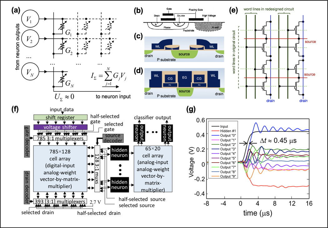
    1. Hasler P, Diorio C, Minch BA and C. and Mead A 1994. Single transistor learning synapses Advances Neural Information Processing Systems 7 817–24
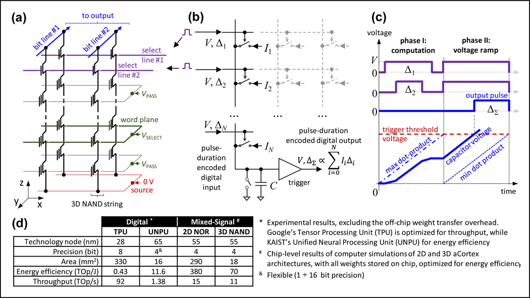
    1. Bavandpour M, Mahmoodi MR, Nili H, Merrikh Bayat F, Prezioso M, Vincent A, Strukov D, and Likharev KK 2019. Mixed-signal neuromorphic inference accelerators: Recent results and future prospects IEEE Int. Electron Device Meeting (San Francisco, CA: ) pp. 20.4.1–4

References (separate from the two page limit)

    1. Shulaker MM et al., “Three-dimensional integration of nanotechnologies for computing and data storage on a single chip,” Nature, vol. 547, no. 7661, pp. 74–78, Jul. 2017. - PubMed
    1. Li C. et al., “Efficient and self-adaptive in-situ learning in multilayer memristor neural networks,” Nat. Commun, vol. 9, no. 1, p. 2385, Jun. 2018. - PMC - PubMed
    1. Romero LP et al., “Training fully connected networks with resistive memories: impact of device failures,” Faraday Discuss, vol. 213, no. 0, pp. 371–391, Feb. 2019. - PubMed
    1. Vatajelu E, Natale GD, and Anghel L, “Special Session: Reliability of Hardware-Implemented Spiking Neural Networks (SNN),” in 2019 IEEE 37th VLSI Test Symposium (VTS), 2019, pp. 1–8.
    1. Liu C, Hu M, Strachan JP, and Li H, “Rescuing memristor-based neuromorphic design with high defects,” in 2017 54th ACM/EDAC/IEEE Design Automation Conference (DAC), 2017, pp. 1–6.

References

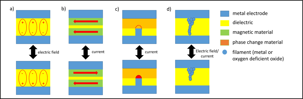
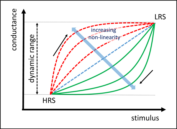
    1. Waser R, Dittmann R, Staikov G, and Szot K, Redox-Based Resistive Switching Memories – Nanionic Mechanisms, Prospects, and Challenges, Advanced Materials 21 2632–2663 (2009). - PubMed
    1. Yang JJ, Strukov DB, and Stewart DR, Memristive Devices for Computing, Nature Nanotechnology 8 13–24 (2013). - PubMed
    1. Sediva E, Bowman WJ, Gonzalez-Rosillo JC, Rupp JLM, Investigation of the Eightwise Switching Mechanism and its Suppression in SrTiO3 Modulated by Humidity and Interchanged Top and Bottom Platinum and LaNiO3 Electrode Contacts, Advanced Electronic Materials 1800566 (2018).
    1. Kubicek M, Schmitt R, Messerschmitt F, Rupp JLM, Uncovering Two Competing Switching Mechanisms for Epitaxial and Ultra-Thin Strontium Titanate-Based Resistive Switching Bits, ACS Nano 9 10737 (2015). - PubMed
    1. Sun W, Gao B, Chi M, Xia Q, Yang JJ, Qian H, Wu H, Understanding Memristive Switching via In Situ Characterization and Device Modeling, Nature Communications 10 3453 (2019). - PMC - PubMed

Bibliography:

    1. Shainline JM, Buckley SM, McCaughan AN, Chiles J, Castellanos-Beltran M, Donnelly CA, Schneider ML, Jafari-Salim A, Mirin RP, and Nam SW, “Superconducting Optoelectronic Loop Neurons”, J. Appl. Phys. 126 044902 (2019).
    1. Schneider ML, Donnelly CA, Russek SE, Baek B, Pufall MR, Hopkins PF, Dresselhaus P, Benz SP, and Rippard WH, “Ultralow power artificial synapses using nanotextured magnetic Josephson junctions”, Sci. Adv. 4 1701329 (2018). - PMC - PubMed
    1. Crotty P, Schult D. and Segall K, “Josephson junction simulation of neurons”, Phys. Rev. E. 82 011914 (2010). - PubMed
    1. Segall K, LeGro M, Kaplan S, Svitelskiy O, Khadka S, Crotty P, and Schult D, “Synchronization dynamics on the picosecond time scale in coupled Josephson junction networks”, Phys. Rev. E. 95 032220 (2017). - PubMed
    1. Furber S, “Large-scale neuromorphic computing systems,” J. Neural Eng, vol. 13, no. 5, p. 051001, Aug. 2016. - PubMed

References (separate from the two page limit)

    1. Maass W 1997. Networks of spiking neurons: The third generation of neural network models Neural Netw. 10 1659–71
    1. Xia Q and Yang JJ 2019. Memristive crossbar arrays for brain-inspired computing Nat. Mater. 18 309–23 - PubMed
    1. Furber SB, Galluppi F, Temple S and Plana LA 2014. The SpiNNaker Project Proc. IEEE; 102 652–65
    1. Merolla PA, Arthur JV, Alvarez-Icaza R, Cassidy AS, Sawada J, Akopyan F, Jackson BL, Imam N, Guo C, Nakamura Y, Brezzo B, Vo I, Esser SK, Appuswamy R, Taba B, Amir A, Flickner MD, Risk WP, Manohar R and Modha DS 2014. A million spiking-neuron integrated circuit with a scalable communication network and interface Science 345 668–73 - PubMed
    1. Davies M, Srinivasa N, Lin T-H, Chinya G, Cao Y, Choday SH, Dimou G, Joshi P, Imam N and Jain S 2018. Loihi: A neuromorphic manycore processor with on-chip learning IEEE Micro 38 82–99

LinkOut - more resources