. 2020 Oct;27(10):925-933.
doi: 10.1038/s41594-020-0479-4. Epub 2020 Jul 22.

Controlling the SARS-CoV-2 spike glycoprotein conformation

Affiliations

Controlling the SARS-CoV-2 spike glycoprotein conformation

Rory Henderson et al. Nat Struct Mol Biol. 2020 Oct.

Abstract

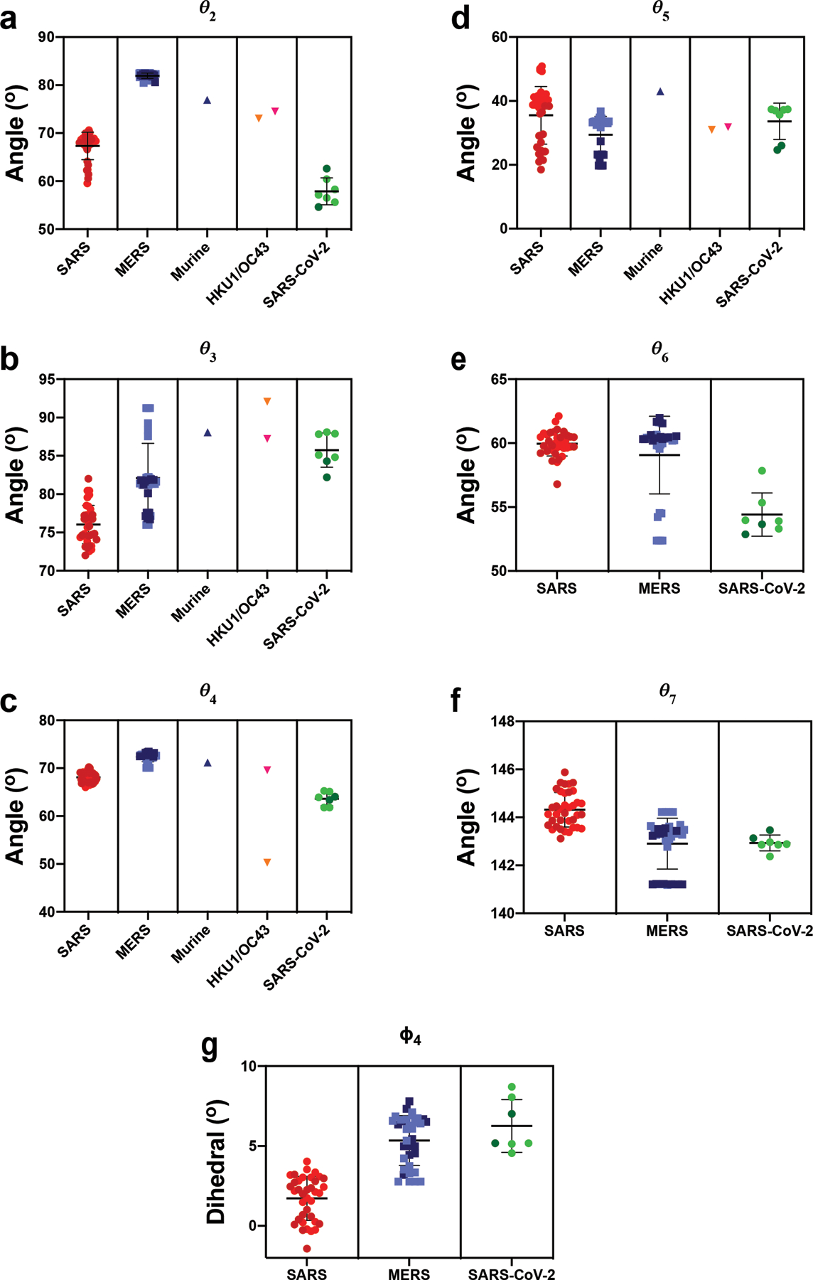
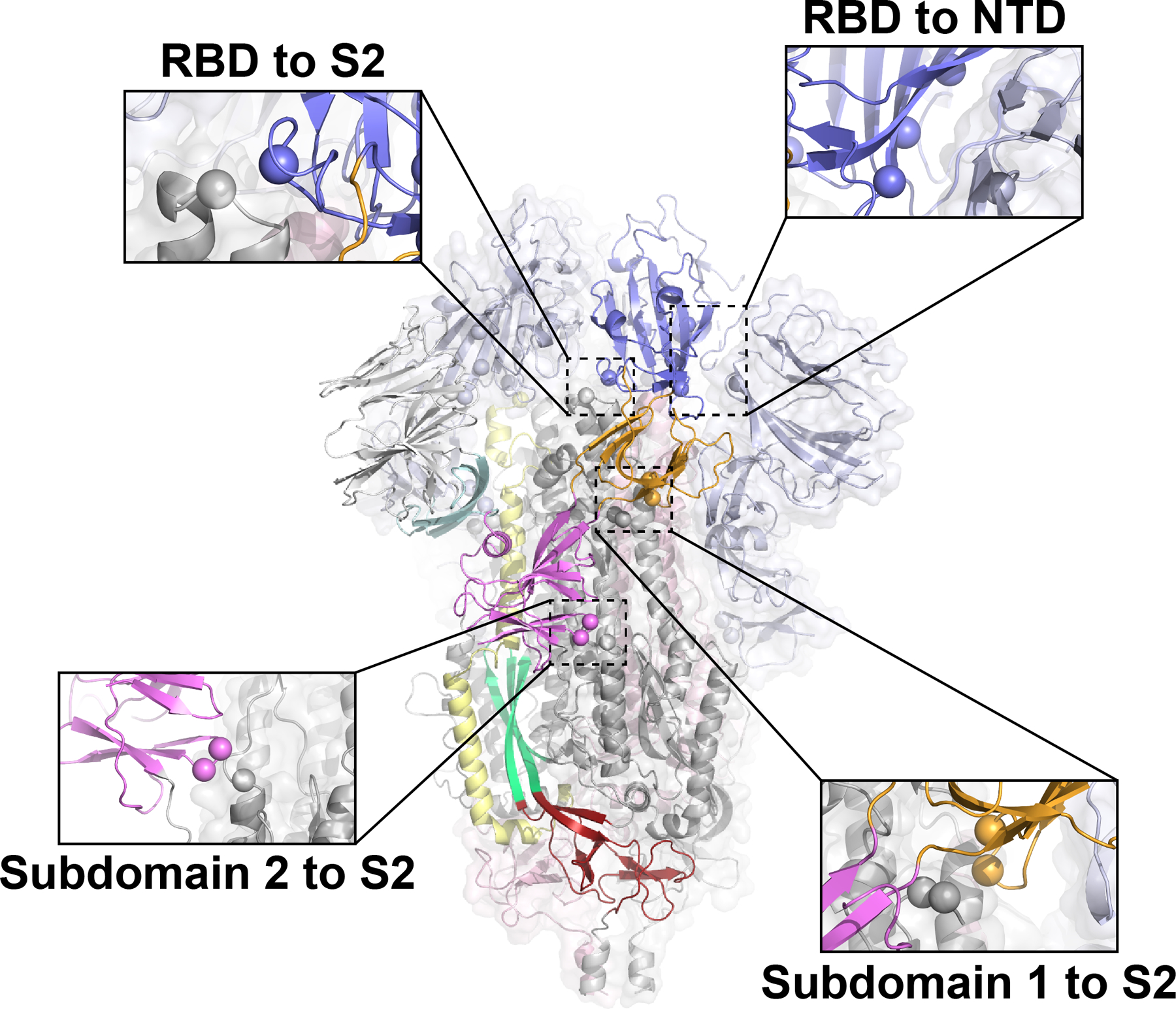
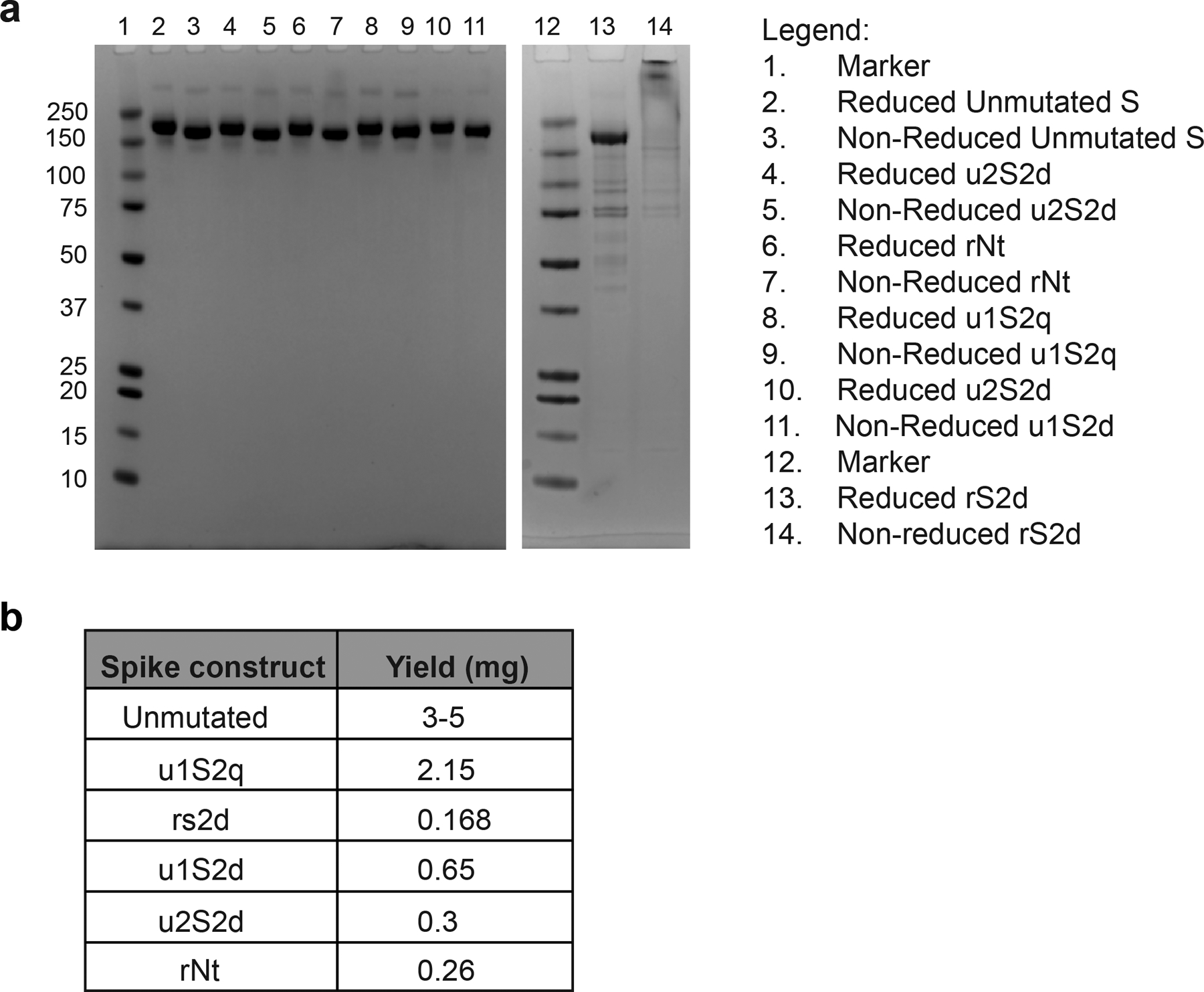
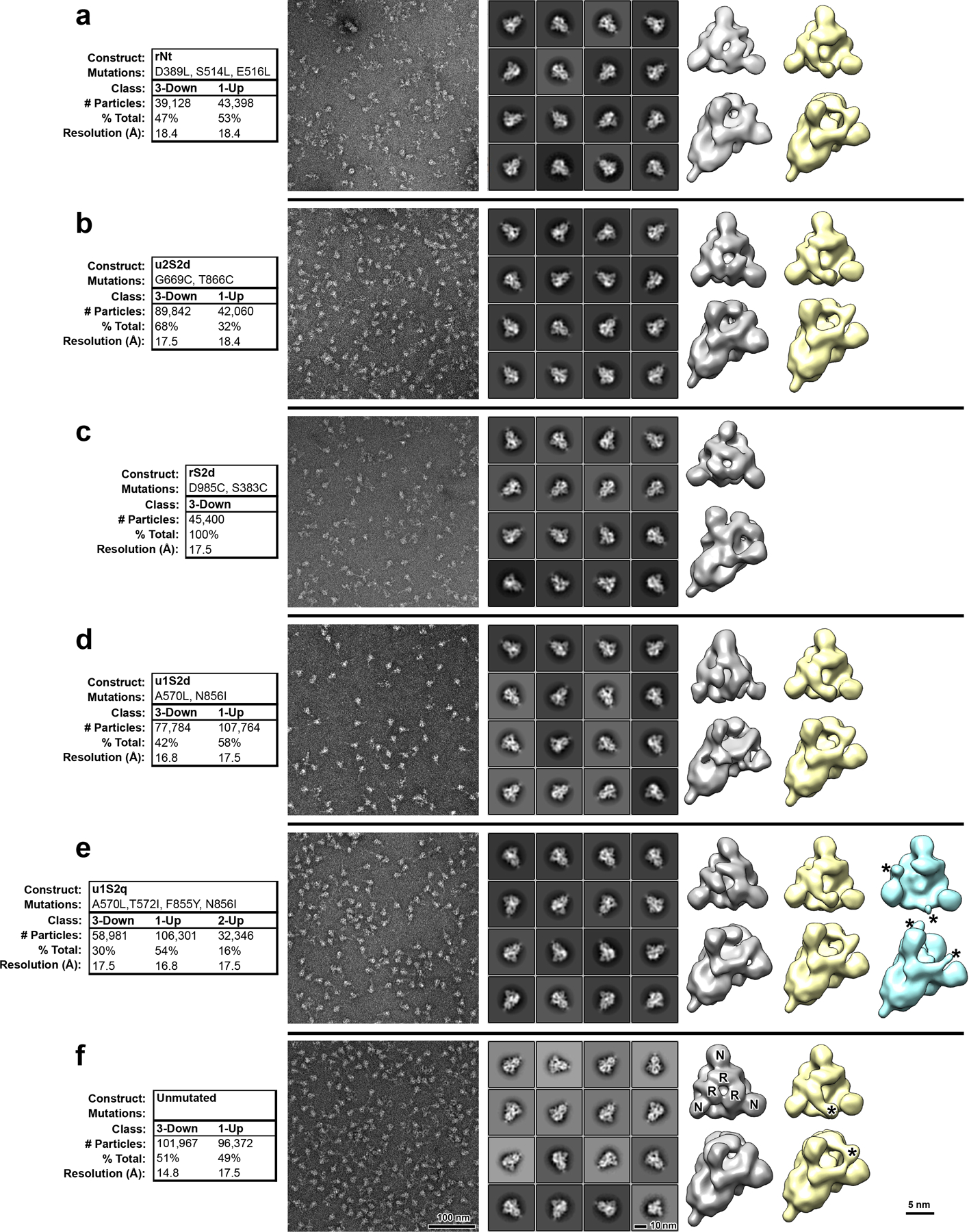
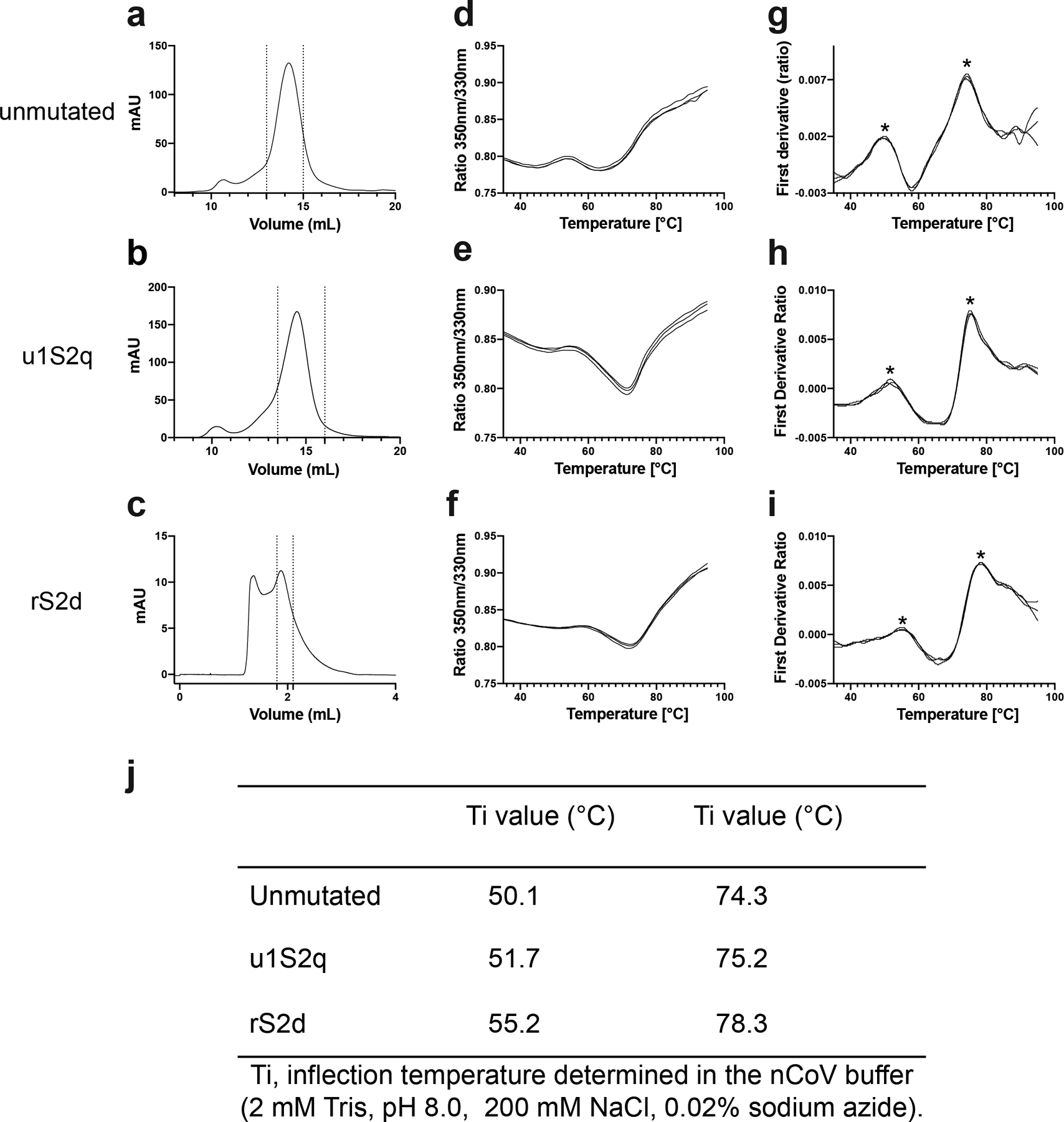
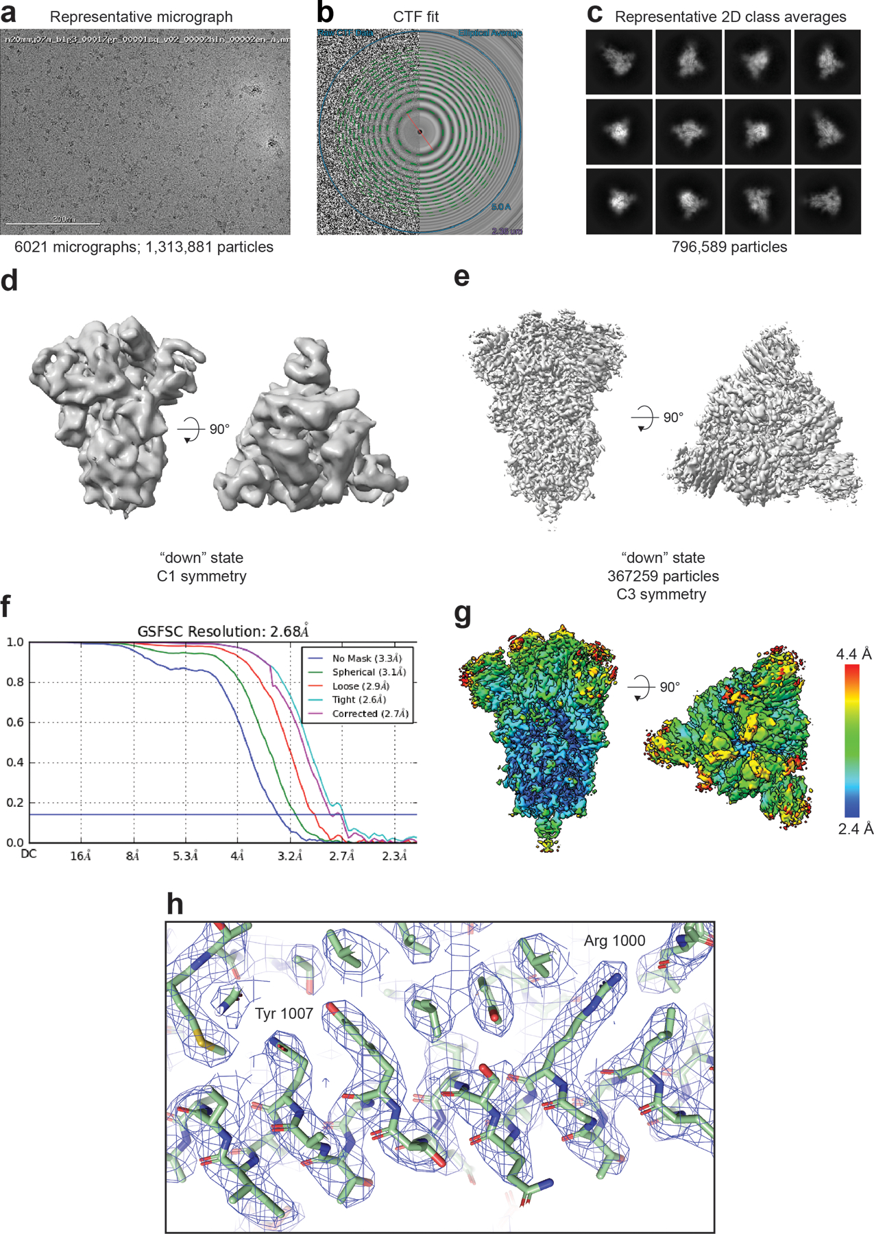
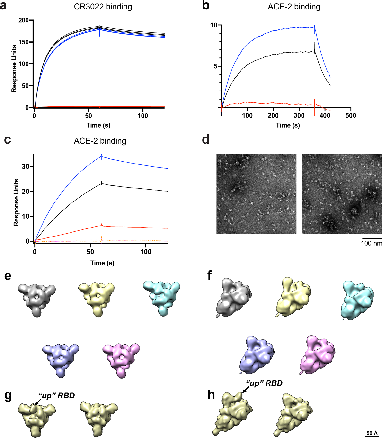
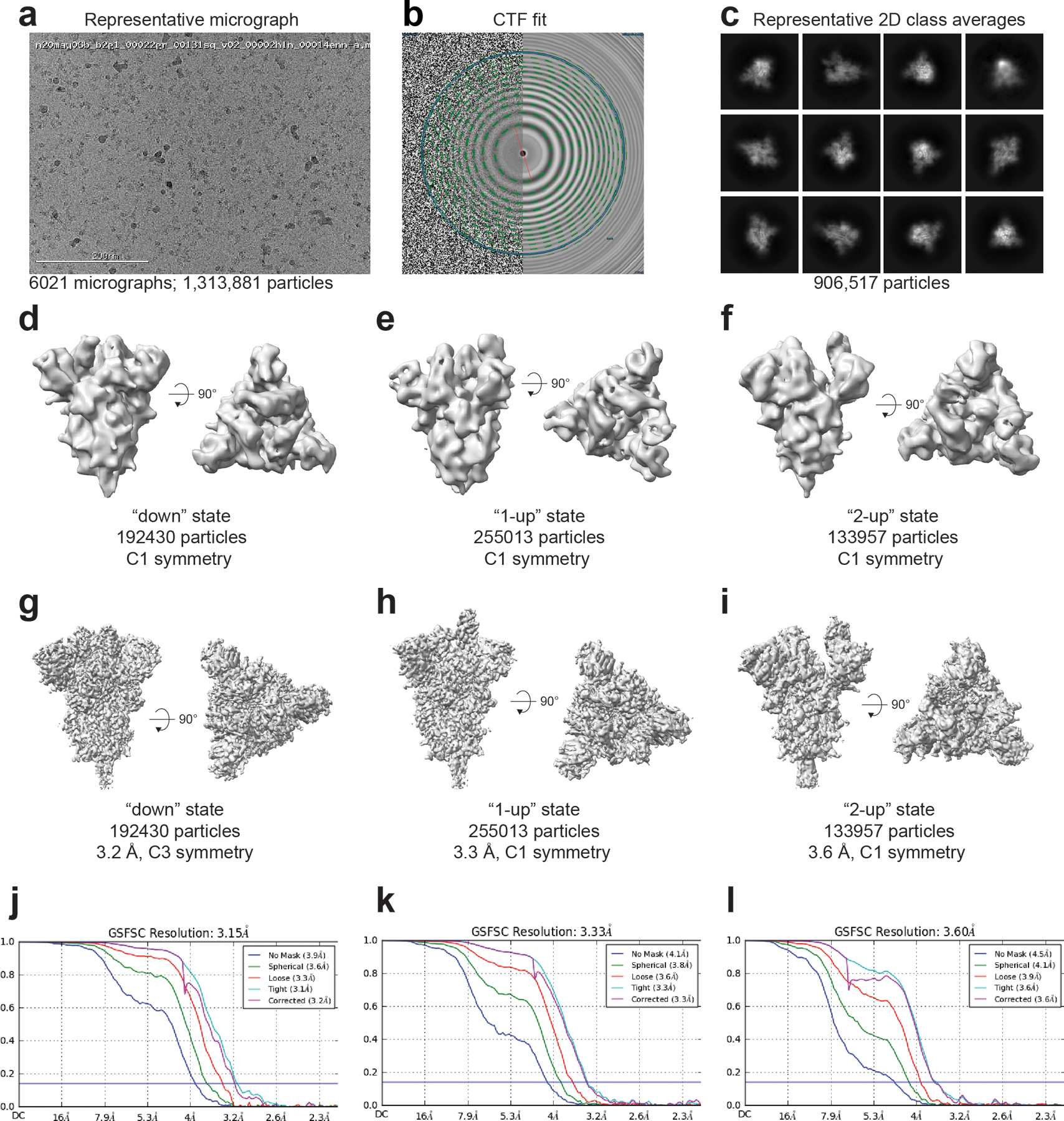
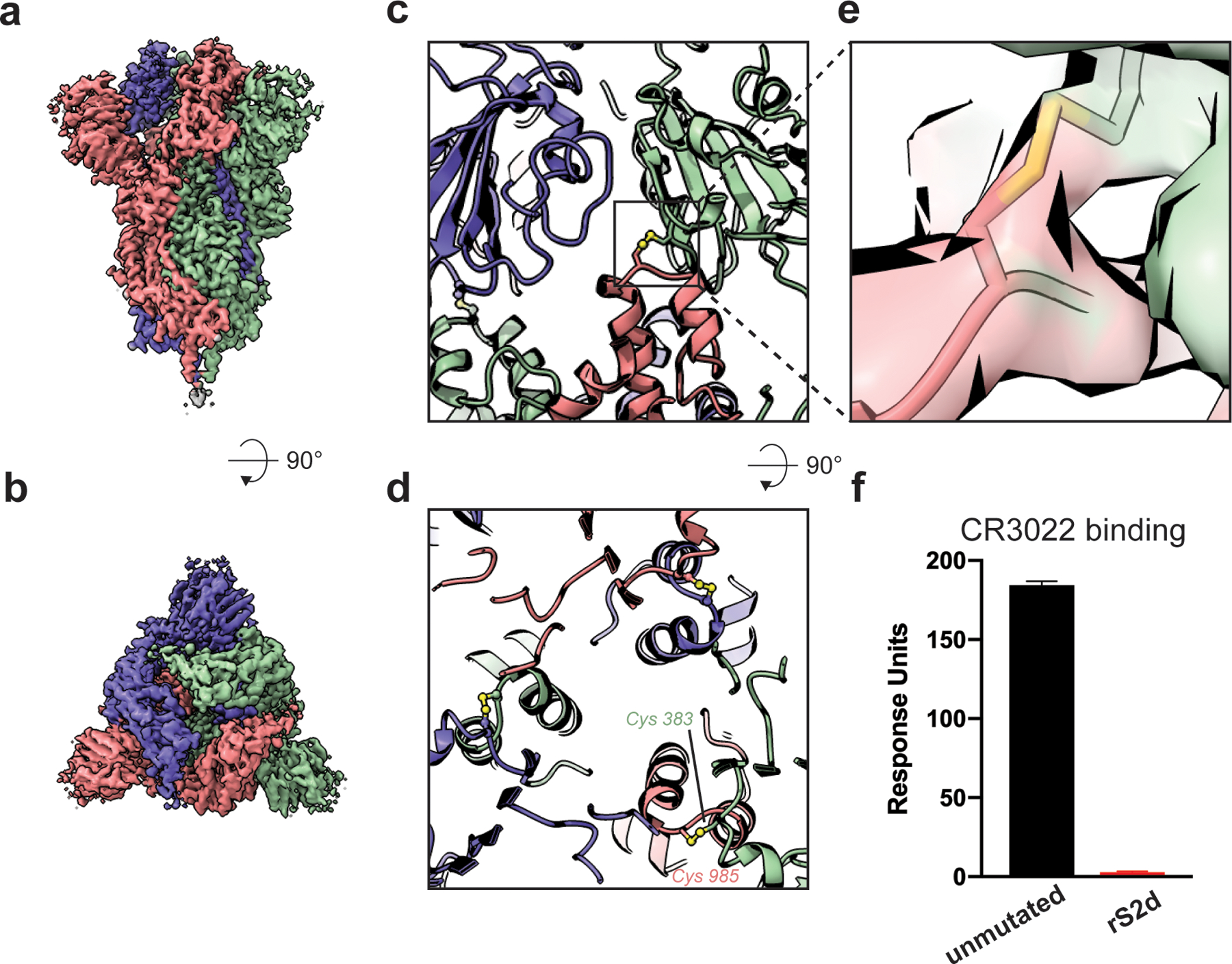
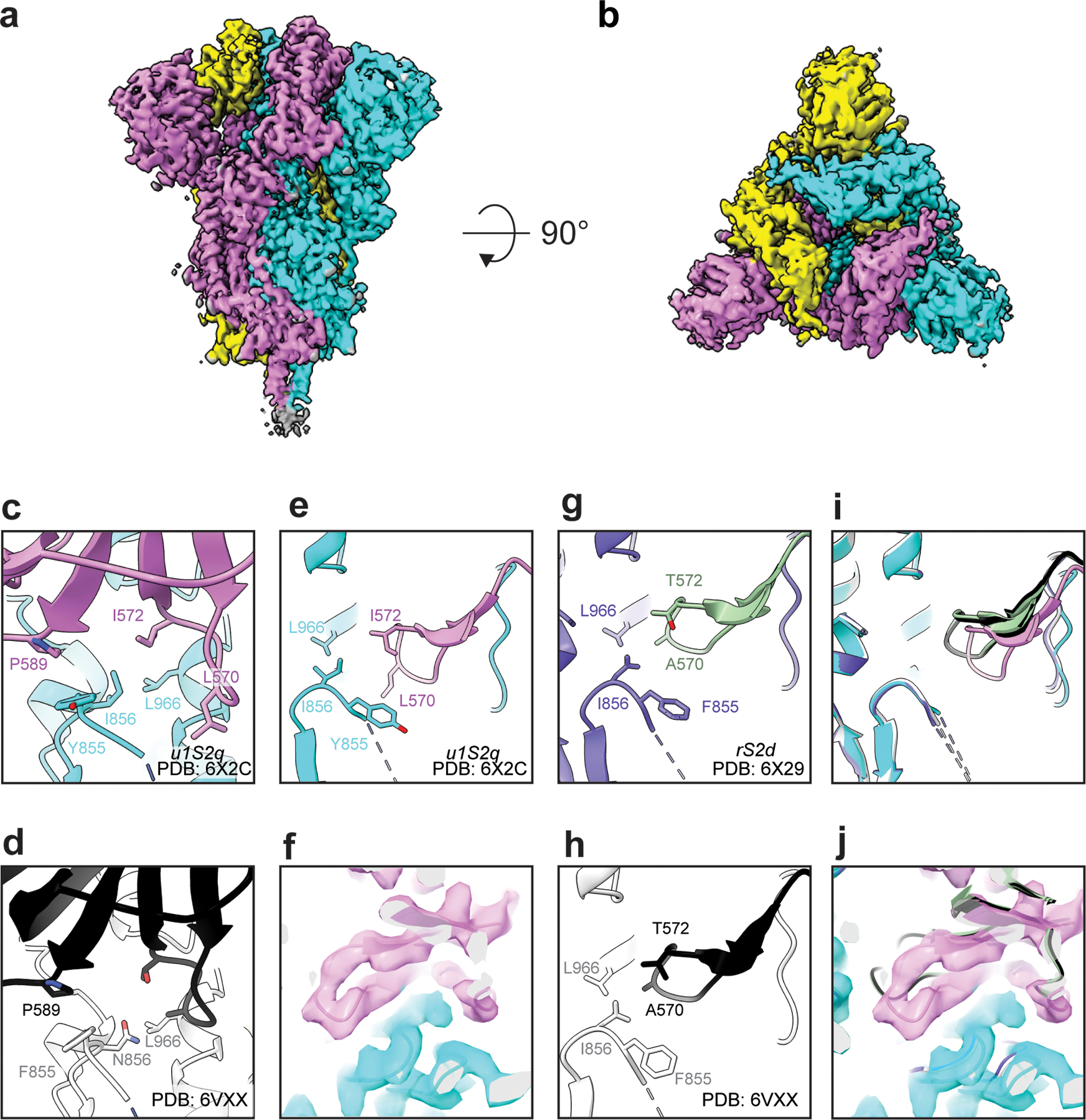
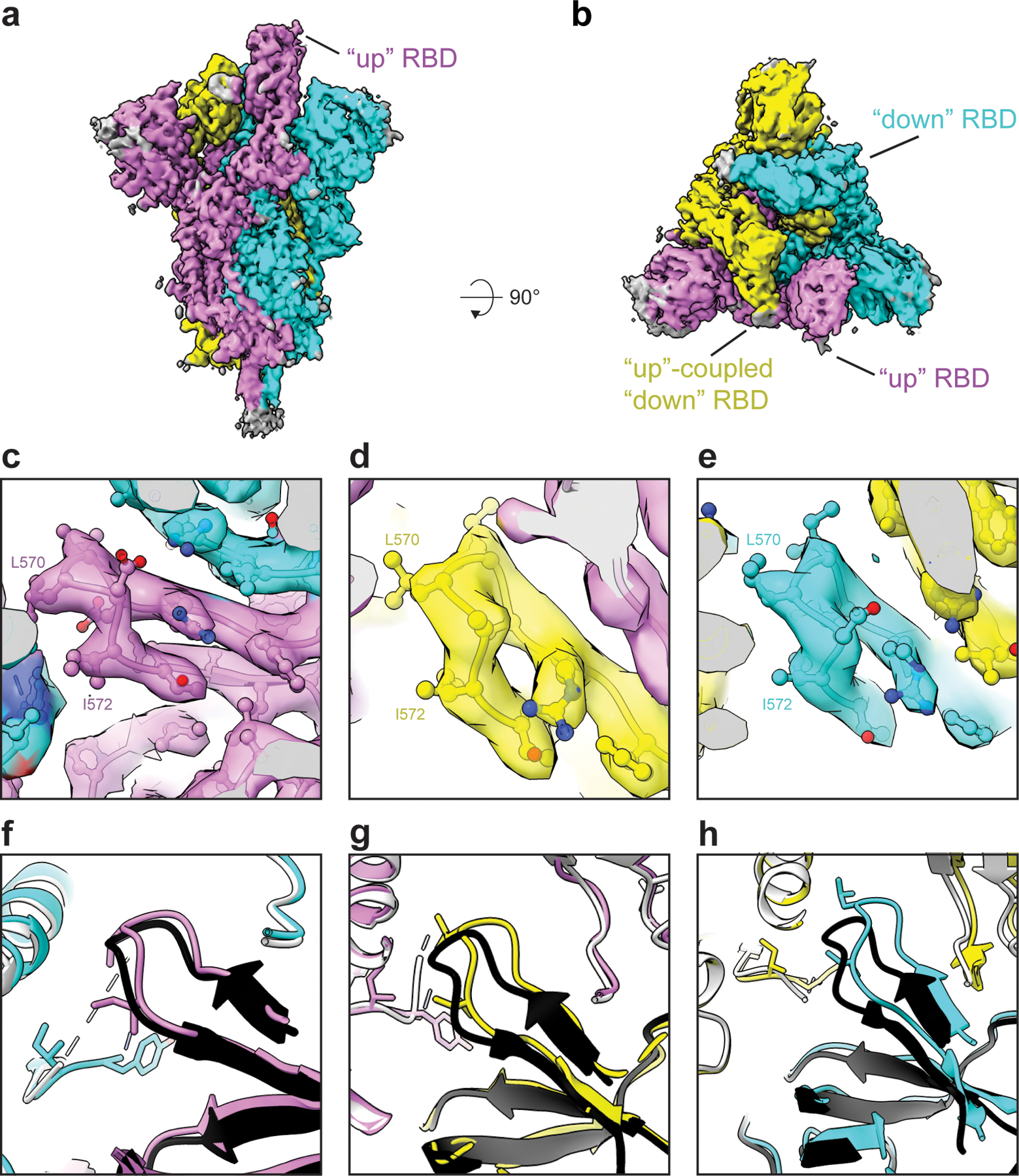
The coronavirus (CoV) spike (S) protein, involved in viral-host cell fusion, is the primary immunogenic target for virus neutralization and the current focus of many vaccine design efforts. The highly flexible S-protein, with its mobile domains, presents a moving target to the immune system. Here, to better understand S-protein mobility, we implemented a structure-based vector analysis of available β-CoV S-protein structures. Despite an overall similarity in domain organization, we found that S-proteins from different β-CoVs display distinct configurations. Based on this analysis, we developed two soluble ectodomain constructs for the SARS-CoV-2 S-protein, in which the highly immunogenic and mobile receptor binding domain (RBD) is either locked in the all-RBDs 'down' position or adopts 'up' state conformations more readily than the wild-type S-protein. These results demonstrate that the conformation of the S-protein can be controlled via rational design and can provide a framework for the development of engineered CoV S-proteins for vaccine applications.


Conflict of interest statement

Competing interests

The authors declare no competing interests.

Figures

Extended Data Fig. 1
Extended Data Fig. 1. β-CoV Vector Analysis.
A) The angle between the vectors connecting the NTD sheet motif centroid and the NTD centroid and the vector connecting the the NTD centroid to the NTD’ centroid. B) The angle between the vectors connecting the NTD’ centroid and the SD2 centroid and the vector connecting the the SD2 centroid to the SD1 centroid. C) The angle between the vectors connecting the NTD centroid and the NTD’ centroid and the vector connecting the the NTD’ centroid to the SD2 centroid. D) The angle between the vectors connecting the SD1 centroid and the RBD centroid and the vector connecting the the RBD centroid to the RBD helix motif centroid. E) The angle between the vectors connecting the NTD’ centroid and the SD2 centroid and the vector connecting the the SD2 centroid to the CD centroid. F) The angle between the vectors connecting the SD2 centroid and the CD centroid and the vector connecting the the CD centroid to the β-sheet motif centroid. G) The dihedral about the SD2 centroid and the CD centroid. Points for SARS, MERS, and SARS-2 in Figure 1 (G)-(J) colored according to ‘up’ (dark) and ‘down’ (light) states according to the color code in the PCA analysis, panels (E) and (F). Individual data points shown as symbols; lines denote mean and s.d. The source data are available in Supplementary Data 1.
Extended Data Fig. 2
Extended Data Fig. 2. Sites identified for differential stabilization of the SARS-CoV-2 S-protein.
Single protomer colored according to Figure 1 with remaining two protomers color according to S1 (light blue) and S2 (grey). Spheres indicate candidate mutation sites.
Extended Data Fig. 3
Extended Data Fig. 3. SDS-PAGE and yields of purified S protein constructs.
A) SDS-PAGE gels of the S protein constructs. B) Yields/L of the S protein constructs
Extended Data Fig. 4
Extended Data Fig. 4. Negative stain electron microscopy analysis of S-protein constructs.
A) Data tables, indicating construct names, mutations, observed classes, number and percent of particles per class and final resolution (gold-standard Fourier-shell correlation, 0.143 level). B) Raw micrographs. C) Representative 2D class averages. D) 3D reconstructions of 3-RBD-down classes, shown in top view, looking down the S-protein 3-fold axis on the left and tilted view on the right. Receptor binding domains and N-terminal domains of first structure marked with R and N, respectively. E) 3D reconstructions of 1-RBD-up classes. Up-RBD is marked with an asterisk. F) 3D reconstruction of 2-RBD-up class. Density for up-RBDs is weak, indicated by asterisks.
Extended Data Fig. 5
Extended Data Fig. 5. Thermostability of the S protein constructs.
A-C) SEC profile of the S proteins. The dotted lines indicate the portion of the peak that was collected for further studies. The unmutated and u1S2q spikes were run on a Superose 6 Increase 10/300 column, and the rS2d spike was run on an analytical Superose 6 Increase 5/150 column. D-I) Unfolding profile curves obtained by intrinsic fluorescence measurements using Tycho NT. 6. D-F) show ratio between fluorescence at 350 nm and 330 nm. G-I) plot the first derivative of this ratio. J) Inflection temperatures for the S proteins. Asterisk mark the inflection temperatures in (G).
Extended Data Fig. 6
Extended Data Fig. 6. Cryo-EM data processing details for rS2d.
A) Representative micrograph. (B) CTF fit (C) Representative 2D class averages. (D) Ab initio reconstruction. (E) Refined map (F) Fourier shell correlation curves (G) Refined map colored by local resolution. (H) Zoomed-in view of the S2 region showing cryo-EM reconstruction as a transparent grey surface, the underlying fitted model in cartoon representation, and residues in ball-and-stick representation.
Extended Data Fig. 7
Extended Data Fig. 7. Binding of spike constructs to ACE-2 and RBD-binding antibody CR3022.
A) SPR sensorgrams of CR3022 antibody binding to unmutated (black line), u1S2q (blue line) or rS2d (red line) spike captured on a strepdavidin chip. B) SPR sensorgrams of ACE-2 (with C-terminal human Fc tag) to unmutated (black line), u1S2q (blue line) or rS2d (red line) spike captured on a strepdavidin chip. C) SPR sensorgrams of binding of unmutated (black line), u1S2q (blue line) or rS2d (red line) spike to ACE-2 (with C-terminal human Fc tag) captured on an anti-mouse Fc surface. The orange and magenta dotted lines are binding curves for rS2d following negative selection over a CR3022 or ACE-2 column, respectively. D) Representative NSEM micrographs of the flow-through after negative selection of the rS2d sample through an ACE-2 column (left) and CR3022 column (right). (E) Top views and (F) side views of 3D classes of particles from the dataset from the CR3022 column-eluted sample. C1 symmetry was used during classification. For comparison, images from cryo-EM maps low-pass filtered to 20 Å of the 1-RBD ‘up’ state (EMD-21457) and 3-RBD ‘down’ state (EMD-21452) are shown in figures (G) top view and (H) side view
Extended Data Fig. 8
Extended Data Fig. 8. Cryo-EM data processing details for u1s2q.
(A) Representative micrograph. (B) CTF fit (C) Representative 2D class averages. (D-F) Ab initio reconstructions for the (D) ‘down’ state, (E) ‘1-up’ state and (F) ‘2-up’ state. (G-I) Refined maps for the (G) ‘down’ state, (H) ‘1-up’ state and (I) ‘2-up’ state. (J-L) Fourier shell correlation curves for the (J) ‘down’ state, (E) ‘1-up’ state and (F) ‘2-up’ state.
Extended Data Fig. 9
Extended Data Fig. 9. Local map resolution for u1s2q.
(A) Refined cryo-EM maps colored by local resolution and (B) Zoom-in image showing region in the S2 domain with the cryo-EM map shown as a transparent surface and underlying fitted model in cartoon representation, with residues shown as balls and sticks. (C) and (D) Same information as presented in panels (A) and (B) but for the 1-RBD ‘up’ state. (E) and (F) Same information as presented in panels (A) and (B) but for the 2-RBD ‘up’ state.
Extended Data Fig. 10
Extended Data Fig. 10. β-CoV Vector Analysis of SARS-2 and SARS-2 Designs.
A-K) Angles and dihedrals for SARS-2 structures and SARS-2 designs depicted in Figure 1c. Individual data points are shown as circles or squares; lines denote mean and s.d.
Figure 1.
Figure 1.. Vector-based analysis of the CoV S-protein demonstrates remarkable variability in S-protein conformation within ‘up’ and ‘down’ states between CoV strains.
A) Cartoon representations of ‘down’ (upper left) and ‘up’ (upper right) state SARS-2 structures (PDB 6VXX and 6VYB, respectively) colored according to the specified domains (lower). B) A single ‘down’ state protomer of the CoV S-protein with labeled domains (PDB 6VXX). The receptor binding domain (RBD) is in its ‘down’ conformation. C) A simplified diagram of the CoV S-protein depicting the centroids and vectors connecting them, with the determine angles (θ) and dihedrals (ϕ) labeled. D) The SARS-2 (left; red, PDB 6VXX) and MERS (right; blue, PDB 6Q04) structures, each with a single protomer depicted in cartoon representation and the remaining two in surface representation. The structures were aligned with the images captured from the same angle for visualization. E) Principal components analysis (PCA) of the SARS and MERS protomers showing measures between S1 and S2 domains. F) Principal components analysis of the SARS, MERS, HKU1, and Murine CoV protomers showing measures only between S1 domains. G) Angle between the SD2-to-SD1 vector and the SD1-to-RBD vector. H) Dihedral about the SD1-to-RBD vector. I) Dihedral about the NTD-to-NTD’ vector. The OC43 value of −162° was adjusted to 197 °(+360 °) for visualization here. J) Dihedral about the SD2-to-SD1 vector. Data points for SARS, MERS, and SARS-2 in g–j colored according to ‘up’ (dark) and ‘down’ (light) states and color code in the PCA analysis in panels e and f. Lines show mean and s.d. The PDB IDs for all structures represented in the PCA and angle/dihedral plots are listed in Supplementary Table 1. K) Structural representation of the (G)-(J) angles and dihedrals overlaid on an alignment between a SARS-2 ‘down’ (cartoon structure with black centroids and lines; PDB 6VXX) and ‘up’ (ribbon structure with red centroids and lines; PDB 6VYB) state protomer. Adjacent protomers are depicted as a transparent surface with S1 (light blue) and S2 (light pink). Source data for graphs here are in Supplementary Data 1.
Figure 2.
Figure 2.. Cryo-EM structures reveal differential stabilization of the S-protein in the mutant ectodomain constructs.
A) The S-protein spike highlighting the two regions of interest for structure and computation-based design (PDB 6VXX). B) The rS2d RBD to S2 locked structure displaying only the all RBD ‘down’ state map. C) The u1S2q SD1-to-S2 mutated structure displaying the all RBD ‘down’ state, the 1-RBD ‘up’ state, and the 2-RBD ‘up’ state. The percentage listed in orange is the sum of particles found in either 1- or 2-RBD ‘up’ states. Each protomer in each map is colored differently with resolutions for these listed to the lower left. Red stars indicate ‘up’ state RBDs.
Figure 3.
Figure 3.. Cryo-EM structure of the rS2d construct locked in the ‘down’ state.
A) Cryo-EM reconstruction of rS2d colored by chain. B) ~90 rotated view of (A). C) Zoom-in view showing engineered disulfide linking the RBD of one protomer and S2 domain of the adjacent protomer. The disulfide bridge is shown as spheres and colored by elements. D) ~90 rotated view of (C). E) Zoom-in view of engineered inter-chain disulfide showing the cryo-EM density as a transparent surface and the underlying model in stick representation. F) Binding of antibody CR3022 to the unmutated (black bar) and rS2d (red bar). The spike was captured on a streptavidin chip and binding to CR3022 IgG was measured by SPR. Data shown are means and s.d. of three technical repeats, and are representative of 5 independent experiments.
Figure 4.
Figure 4.. Cryo-EM structures of RBD ‘down’ S proteins reveal differential stabilization of domain positions.
Cryo-EM reconstruction of u1S2q colored by chain. B) ~90 rotated view of (A). C) Zoomed-in view of the region containing the mutations, showing proximity of the F855Y and N856I residue loop to the S2 residue L966 and S1 residue P589. D) Similar region shown in (C) but for the unmutated structure (PDB 6VXX). (E) Zoom-in view of the region containing the mutations at a different angle than the one shown in (C), and (F) the loop containing the A570L and T572I mutations with cryo-EM map shown as a transparent surface and fitted model shown in cartoon representation.(G and H) Similar region shown in (E) but for (G) the rS2d structure (PDB ID: 6X29) and (H) the unmutated structure (PDB 6VXX). (I) Overlay of the three ‘down’ state structures and (J) with the cryo-EM reconstruction for the ‘down’ state for the u1S2q construct.
Figure 5.
Figure 5.. Cryo-EM structure of the u1S2q 1 RBD ‘up’ state reveals increasing relaxation of the triggered RBD toward the unmutated structure.
Cryo-EM reconstruction of u1S2q 1 RBD “up” state colored by chain. B) ~90 rotated view of (A). C-E) Zoomed-in views of the region containing the A570L and T572I mutations in each of the protomers of the asymmetric 1-RBD “up” spike. The cryo-EM reconstruction is shown as a transparent surface with the underlying fitted model in cartoon representation and residues as balls and sticks. (F-H) The 1-RBD “up” structure of the unmutated spike (PDB 6VYB) (shown in black and grey) superimposed on the u1S2q 1-RBD “up” structure (PDB 6X2B, this study), colored according to the coloring scheme in (A).
Figure 6.
Figure 6.. Structure of the u1S2q 2 RBD ‘up’ state.
A) Cryo-EM reconstruction of u1S2q colored by chain. B) ~90 rotated view of (A). C) Binding of antibody CR3022 to (top) the unmutated construct and (bottom) u1s2q. Binding of CR3022 Fab to the S proteins was measured by SPR using single cycle kinetics. The black lines are the binding sensorgrams and the red lines show fit of the data to a 1:1 Langmuir binding model. (D) CR3022 (shown as a semi-transparent, gray surface) modeled on the “1-up” u1S2q structure (left) and the “2-up” u1S2q structure (right) using RBD in the crystal structure of the CR3022-RBD complex (PDB 6W41) to superimpose on the “up” RBD of the u1S2q structures. Locations of potential clashes are indicated in each model.

Update of

References

    1. Kirchdoerfer RN et al. Pre-fusion structure of a human coronavirus spike protein. Nature 531, 118–121, doi:10.1038/nature17200 (2016). - DOI - PMC - PubMed
    1. Hoffmann M et al. SARS-CoV-2 Cell Entry Depends on ACE2 and TMPRSS2 and Is Blocked by a Clinically Proven Protease Inhibitor. Cell 181, 271–280 e278, doi:10.1016/j.cell.2020.02.052 (2020). - DOI - PMC - PubMed
    1. Wrapp D et al. Cryo-EM structure of the 2019-nCoV spike in the prefusion conformation. Science 367, 1260–1263, doi:10.1126/science.abb2507 (2020). - DOI - PMC - PubMed
    1. Yuan Y et al. Cryo-EM structures of MERS-CoV and SARS-CoV spike glycoproteins reveal the dynamic receptor binding domains. Nature Communications 8, 15092, doi:10.1038/ncomms15092 (2017). - DOI - PMC - PubMed
    1. Gui M et al. Cryo-electron microscopy structures of the SARS-CoV spike glycoprotein reveal a prerequisite conformational state for receptor binding. Cell Research 27, 119–129, doi:10.1038/cr.2016.152 (2017). - DOI - PMC - PubMed

Publication types

MeSH terms

Substances

LinkOut - more resources