Review
. 2020 Jun 4;9(6):667-682.
doi: 10.1002/open.201900367. eCollection 2020 Jun.

Artificial Signal Transduction

Affiliations
Review

Artificial Signal Transduction

Robert Bekus et al. ChemistryOpen. .

Abstract

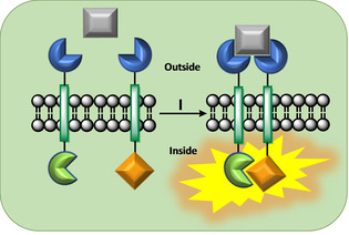
Communication between and inside cells as well as their response to external stimuli relies on elaborated systems of signal transduction. They all require a directional transmission across membranes, often realized by primary messenger docking onto external receptor units and subsequent internalization of the signal in form of a released second messenger. This in turn starts a cascade of events which ultimately control all functions of the living cell. Although signal transduction is a fundamental biological process realized by supramolecular recognition and multiplication events with small molecules, chemists have just begun to invent artificial models which allow to study the underlying rules, and one day perhaps to rescue damaged transduction systems in nature. This review summarizes the exciting pioneering efforts of chemists to create simple models for the basic principles of signal transduction across a membrane. It starts with first attempts to establish molecular recognition events on liposomes with embedded receptor amphiphiles and moves on to simple transmembrane signaling across lipid bilayers. More elaborated systems step by step incorporate more elements of cell signaling, such as primary and secondary messenger or a useful cellular response such as cargo release.

Keywords: cell membranes; fluorescence; liposomes; messengers; signal transduction.


Conflict of interest statement

The authors declare no conflict of interest.

Figures

Figure 1
Figure 1
(a) Schematic representation of a lipid bilayer. (b) Chemical structure of the lipids, which are used for signaling assemblies below. The structural elements of the amphiphilic molecules are colored: The glycerol backbone (light orange) connects hydrophilic head group (light green) to hydrophobic acyl chains (light blue).
Figure 2
Figure 2
(a) Examples of artificial receptor systems for selective molecular recognition on the vesicle surface. (b) Chemical structure of the employed amphiphilic receptor molecules. (c) Selective binding partners and cationic lipid for vesicle recognition: Illustration of copper(II) ion, coumarin ligand 4 and cationic lipid (DOTAP) 5.
Figure 3
Figure 3
General RTK signaling principle: (I) A primary messenger (grey) docks onto two embedded receptor sites (dark blue), bridges both receptor units and initiates a chemical reaction inside the vesicle.
Figure 4
Figure 4
Illustration of the signaling pathway: Structure of synthetic transducers (6, 7 and 9) which are embedded in a lipid bilayer. (I) External reduction of cysteine‐2‐pyridinyl disulfide (7) gives 9 with a thiol head group. (II) Oxidation of both thiol head moieties (in 6 and 9) by potassium ferricyanide bridges both TM units outside the liposome and initiates the thiol‐disulfide reaction (SN2‐reaction) inside the membrane. (III) Triggered release of pyridine‐2‐thiol as a UV/Vis active compound (341 nm).
Figure 5
Figure 5
(a) Cartoon of the signaling pathway with both transmembrane units in a lipid bilayer. (I) The general concept shows the designed release of thiopyridine from the precursor 12. (II) Docking of the primary messenger followed by the induced SN2‐type displacement of thiopyridine results in disulfide‐bridged TM unit 13. (b) External reduction of oppositely orientated disulfide 11 by a water‐soluble phoshine. (c) Background‐, signal‐, and reduction‐dependence on the composition of the lipid. (d) Key experiments in which both TM units are embedded in the mixed DMPC/DPPC vesicles: the double absorption increase is a result of the consecutive addition of the primary messenger and the reducing agent. (e) Messenger‐filled liposomes are exposed to ninhydrin (no messenger penetration for 45 min) and to Triton X (lysis of the vesicle). (f) Conceivable inter‐vesicle reaction by DET crosslink.
Figure 6
Figure 6
(a) Illustration of the signaling concept with embedded transmembrane unit 14 in a lipid bilayer. (I) External addition of CuCl2 leads to the formation of a Cu(14)2 complex and quenches the initial dansyl fluorescence on the exterior side of the lipid bilayer. (II) Penetration of a copper(II) ion across the model membrane results in subsequent coordination of CuII to a preorganized tetradentate ligand Cu(14)2 (cooperative binding event) inside the vesicle (second fluorescence quenching). (b) Transition‐metal receptor system for selective copper(II) ion recognition. (I) Similarly, formation of the Cu(2)2 complex is quenching the dansyl fluorescence at the exterior vesicle surface. (II) Diffusion of a CuII ion through the phospholipid bilayer is now leading to a non‐cooperative binding event and the formation of another quenched Cu(2)2 complex inside the vesicle.
Figure 7
Figure 7
(a) Left: Fluorescence emission spectrum showing the induced FRET effect after DET addition to the doped vesicles. Right: cartoon of the signaling complex inside the lipid bilayer. (b) Potential unwanted U‐shaped conformation of bisamphiphilic TM units 15 and 16 – no signaling. (c) Left: Fluorescence spectrum of the multi FRET system before (black curve) and after DET addition (red curve). The black curve demonstrates an eosin‐induced permanent multi‐FRET effect (excitation 280 nm) on the vesicle surface. DET addition triggers a new FRET effect inside the vesicle (cellular response, excitation 280 nm), with the typical donor emission decrease and acceptor emission increase, but without any enhancement of the eosin emission intensity expected from U‐shaped TM units (enhanced external multi‐FRET). Therefore, the U‐shaped complex could be excluded. Center: Cartoon of the signaling FRET (I) and the permanent multi‐FRET complex (II) observed in the ternary fluorophore system. Right: Vesicle suspension with embedded TM‐units (15 and 16) and free eosin: Cuvette before and after DET addition – signaling visible with the naked eye.
Figure 8
Figure 8
Cross‐section of a supramolecular assembly for transmembrane signal transduction and amplification, showing the controlled translocation of a membrane‐embedded transducer. An external input signal (orange) is recognized on the receptor head group and initiates the translocation process of the transducer to the inner aqueous volume, where the pro‐catalyst (red) becomes active (green) for multiple conversions of an encapsulated substrate (grey) to the second messenger – the intra‐vesicular response (yellow). (Langton et al., Nat. Chem. 2017)
Figure 9
Figure 9
(a) The translocation pathway: In the OFF state the receptor head group (blue) is charged and membrane‐impermeable. (I) The chemical input signal (OH) deprotonates the head group to a neutral species and renders the transducer membrane‐permeable (purple). (II) Translocation of the transducer is followed by complex formation between the pro‐catalyst (pink) and an encapsulated zinc(II)‐cation leading to the active catalyst (green). (III) The intra‐vesicular non‐fluorescent substrate (grey) is hydrolyzed assisted by zinc(II)‐catalysis to give a fluorescent product (yellow). (b) The chemical structure of the transducer carries a morpholine head and a pyridine oxime tail moiety. The central part consists of a lithocholic acid derivative (grey) and acts as a lipophilic anchor inside the lipid bilayer. 17⋅H+ represents the transducer in the OFF state, while 17⋅Zn2+ depicts the ON state. (Langton et al., Nat. Chem. 2017)
Figure 10
Figure 10
Detection of signal transduction by pH‐responsive translocation: (a) Time‐dependent changes in fluorescence emission at 510 nm (excited at 415 nm): Signaling assembly with incorporated transducer 17⋅H+ in the OFF state (red curve); signaling system with embedded 17⋅Zn2+ in the ON state (green curve). Liposome vesicle with encapsulated zinc chloride and substrate 18, but without transducer 17 (black curve). (b) Fluorescent vesicles detectable by TIRF microscopy: top: ON state; bottom: OFF state. (Langton et al., Nat. Chem. 2017)
Figure 11
Figure 11
(a) Time‐dependent changes in fluorescence emission: Fluorescence increase at 510 nm (excitation 415 nm) in the presence (+) und absence (−) of 20 and EDTA. (b) Background metal cation binding equilibria (top) and assumed mechanism for the signal transduction (bottom): (I) Negligible Cu2+‐phenanthroline complex dissociation in absence of EDTA. (II) Hardly any translocated transducers 20 are turned to the ON state for catalyzed substrate conversion. (III) External addition of EDTA immediately traps Cu2+ ions from the phenanthroline moiety and enables translocation of the neutral transducer. (IV) Zn2+ binding to the pyridine oxime tail switches the transducer to the ON‐state. (c) Chemical structure of the transducer as CuII‐phenanthroline 20⋅Cu2+ (initial OFF‐state) and zinc‐pyridine oxime complex 20⋅Zn2+ (ON‐state). (Langton et al., J. Am. Chem. Soc. 2017)
Figure 12
Figure 12
Input signal‐controlled reversible translocation mechanism: successive additions of EDTA and CuCl2 to the extra‐vesicle solution switch signaling transducer between its OFF and ON state. (Langton et al., J. Am. Chem. Soc. 2017)
Figure 13
Figure 13
Signal transduction mechanism which triggers cargo release from vesicles. (a) Illustration of the signaling pathway. The primary messenger switches the state of the external transducer head group from polar (blue) to apolar (purple), allowing its translocation to the inside of the liposome. Zn2+‐binding to the inner tailgroup (rose) activates the catalyst (green). (b) Catalytic surfactant generation. The catalyst hydrolyzes 21 (grey) and generates the surfactant 23 (yellow). (c) Cargo release. The surfactant enters the lipid bilayer which in turn enhances the permeability of the membrane for polar solutes, enabling cargo release (pink). (Langton et al., J. Am. Chem. Soc. 2017)

References

    1. Lemmon M. A., Schlessinger J., Cell 2010, 141, 1117–1134. - PMC - PubMed
    1. Simons K., Toomre D., Nat. Rev. Mol. Cell Biol. 2000, 1, 31–41. - PubMed
    1. Cebecauer M., Spitaler M., Sergé A., Magee A. I., J. Cell Sci. 2010, 123, 309–320. - PubMed
    1. Ségaliny A., Tellez-Gabriel M., Heymann M.-F., Heymann D., J. Bone Oncol. 2015, 4, 1–12. - PMC - PubMed
    1. Hanlon C. D., Andrew D. J., J. Cell Sci. 2015, 128, 3533–3542. - PMC - PubMed

LinkOut - more resources