. 2020 Dec 1;93(1116):20200595.
doi: 10.1259/bjr.20200595. Epub 2020 Aug 5.

Normal pulmonary venous anatomy and non-anomalous variations demonstrated on CT angiography: what the radiologist needs to know?

Affiliations

Normal pulmonary venous anatomy and non-anomalous variations demonstrated on CT angiography: what the radiologist needs to know?

Niraj Nirmal Pandey et al. Br J Radiol. .

Abstract

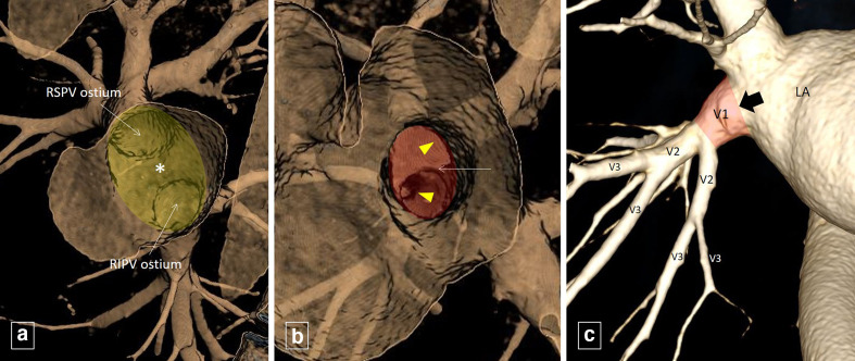
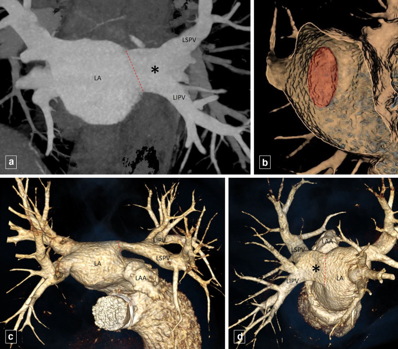
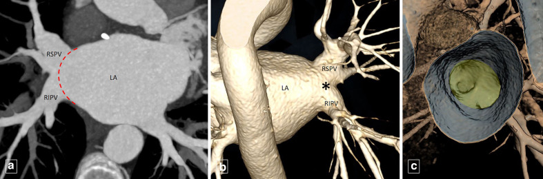
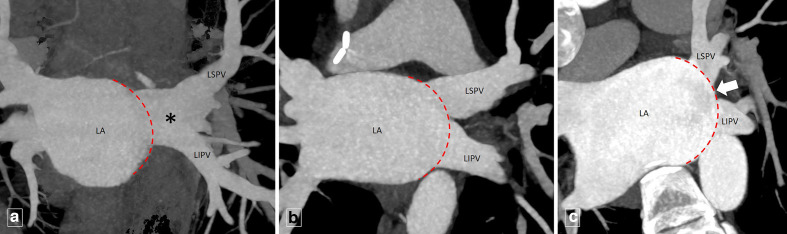
Variations in pulmonary venous anatomy (in the absence of any anomalous pulmonary venous connections) is not uncommon. Commonly occurring variations include presence of conjoined pulmonary veins (PV), supernumerary PVs and ostial PVs. Variant PV anatomy is often asymptomatic; however, it may assume importance in the pre-procedural planning prior to cardiothoracic surgeries and radiofrequency catheter-directed ablation for PV isolation. It is therefore important that the radiologist is aware of the conventional normal and variant PV anatomy in addition to obvious abnormalities like anomalous PV drainage or PV stenosis/ occlusion. Multidetector CT (MDCT) is often used as the first-line imaging modality for pre-procedural PV mapping as it provides high quality images with short acquisition times and availability of numerous post-processing tools.This pictorial review focusses on the MDCT-based PV imaging describing the reporting nomenclature, the conventional normal as well as non-anomalous variant PV anatomy along with their clinical significance.


Figures

Figure 1.
Figure 1.
Endoluminal view (A) showing the RSPV and RIPV ostium with the interposed left atrial wall between the two ipsilateral ostia (intervenous saddle, indicated by *) forming the ‘right pulmonary venous inflow vestibule’ (shaded in yellow). Endoluminal view (B) of the RSPV ostium (shaded in red) show the venous wall (intravenous saddle, indicated by thin white arrow) interposed between the branches (arrowheads) of RSPV. Volume rendered image (C) shows the distal RIPV being divided into segments (labelled V1, V2 and so on in a sequential fashion) between its branch points, starting from the its ostium (thick black arrow) moving away from left atrium (LA). The V1 segment (shaded in red) is referred to as the pulmonary venous trunk. RIPV, right inferior pulmonary vein; RSPV, right superior pulmonary vein.
Figure 2.
Figure 2.
Coronal maximum intensity projection image (A) shows the LSPV and IPV joining each other forming a common channel (*) before reaching the LA, resulting in a single pulmonary veno-atrial junction (dotted red line). Endoluminal view (B) shows the single ellipticalleft pulmonary venous ostium (shaded in red). Volume rendered images (C, D) depict the conjoined vein (*) draining the LSPV and LIPV into the LA. LAA, left atrial appendage; LIPV, left inferior pulmonary vein; LSPV, left superior pulmonary vein.
Figure 3.
Figure 3.
Coronal maximum intensity projection image (A) and volume rendered image (B) shows theRSPV and RIPV joining each other forming a conjoined PV trunk (*, in B) having a significantly shorter length and a significantly larger diameter before reaching the LA. The red dashed line in A) represents the extrapolation of the shape of LA adjacent to the pulmonary venous ostia to define the expected atriopulmonary venous junction. Endoluminal view (C) shows the single broad right pulmonary venous ostium (shaded in yellow). LA, left atrium; RIPV, right inferior pulmonary vein; RSPV, right superior pulmonary vein.
Figure 4.
Figure 4.
Coronal maximum intensity projection image (A, B, C) of different patients demonstrate the extrapolation of the LA shape adjacent to the left-sided pulmonary venous ostia to define the expected atriopulmonary venous junction (dashed red lines). (A) shows the (LSPV and LIPV joining each other (before reaching the dashed red lines) forming a conjoined vein (*). (B) shows separate LSPV and LIPV ostium with no intervening LA wall while (C) shows separate LSPV and LIPV ostium with intervening LA wall (thick white arrow). LA, left atrial; LIPV, left inferior pulmonary vein; LSPV, left superior pulmonary vein.
Figure 5.
Figure 5.
Coronal oblique maximum intensity projection image(A) and volume rendered image (B) shows the right middle vein (RMV) draining directly into the LA, separate from the RSPV and RIPV. (B,) shows the veins draining the medial and lateral segment of right middle lobe joining to form the RMV. Endoluminal view (C) shows the supernumerary ostium (*) of RMV between the RSPV and RIPV ostium. LA, left atrium; RIPV, right inferior pulmonary vein; RSPV, right superior pulmonary vein.
Figure 6.
Figure 6.
Coronal oblique (A) and sagittal oblique (B) maximum intensity projection imagesand volume rendered image (C) shows the right “top” vein (thick black arrow) draining directly into the LA, separate from the RSPV and RIPV. Endoluminal view (D) shows the supernumerary ostium (arrowhead) of the right “top” vein supero-medial to the RSPV ostium. LA, left atrium; RIPV, right inferior pulmonary vein; RSPV, right superior pulmonary vein.
Figure 7.
Figure 7.
Coronal oblique maximum intensity projection image (A) and volume rendered image (B) shows early branching of the right middle lobe vein (*) from the RSPV within 5 mm of the RSPV ostium. Endoluminal view (C) shows the right middle lobe vein ostium (curved arrow) within 5 mm of the RSPV ostium (shaded in yellow). LA, left atrium; RIPV, right inferior pulmonary vein.
Figure 8.
Figure 8.
Volume rendered image (A) shows early branching of the superior segmental branch of right lower lobe (*) from the RIPV within 5 mm of the RIPV ostium. Endoluminal view (B) shows its ostium (curved arrow) within 5 mm of the RIPV ostium (shaded in yellow). RIPV, right inferior pulmonary vein.

References

    1. Hassani C, Saremi F. Comprehensive cross-sectional imaging of the pulmonary veins. Radiographics 2017; ; 37: 1928–54Nov-Dec. doi: 10.1148/rg.2017170050 - DOI - PubMed
    1. Rajiah P, Kanne JP. Computed tomography of pulmonary venous variants and anomalies. J Cardiovasc Comput Tomogr 2010; ; 4: 155–63May-Jun. doi: 10.1016/j.jcct.2010.01.016 - DOI - PubMed
    1. Lacomis JM, Wigginton W, Fuhrman C, Schwartzman D, Armfield DR, Pealer KM. Multi-detector row CT of the left atrium and pulmonary veins before radio-frequency catheter ablation for atrial fibrillation. Radiographics 2003; 23 Spec No : S35–48Oct;23 Spec No:S35-48; discussion. doi: 10.1148/rg.23si035508 - DOI - PubMed
    1. Marom EM, Herndon JE, Kim YH, McAdams HP. Variations in pulmonary venous drainage to the left atrium: implications for radiofrequency ablation. Radiology 2004; 230: 824–9. doi: 10.1148/radiol.2303030315 - DOI - PubMed
    1. Ho SY. Pulmonary vein ablation in atrial fibrillation: does anatomy matter? J Cardiovasc Electrophysiol 2003; 14: 156–7. doi: 10.1046/j.1540-8167.2003.02551.x - DOI - PubMed

MeSH terms