. 2020 Sep 18;295(38):13277-13286.
doi: 10.1074/jbc.RA120.014150. Epub 2020 Jul 28.

Discovery of a heme-binding domain in a neuronal voltage-gated potassium channel

Affiliations

Discovery of a heme-binding domain in a neuronal voltage-gated potassium channel

Mark J Burton et al. J Biol Chem. .

Erratum in

  • Correction: Discovery of a heme-binding domain in a neuronal voltage-gated potassium channel.
    Burton MJ, Cresser-Brown J, Thomas M, Portolano N, Basran J, Freeman SL, Kwon H, Bottrill AR, Llansola-Portoles MJ, Pascal AA, Jukes-Jones R, Chernova T, Schmid R, Davies NW, Storey NM, Dorlet P, Moody PCE, Mitcheson JS, Raven EL. Burton MJ, et al. J Biol Chem. 2022 Mar;298(3):101754. doi: 10.1016/j.jbc.2022.101754. Epub 2022 Mar 2. J Biol Chem. 2022. PMID: 35247676 Free PMC article. No abstract available.

Abstract

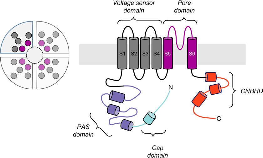
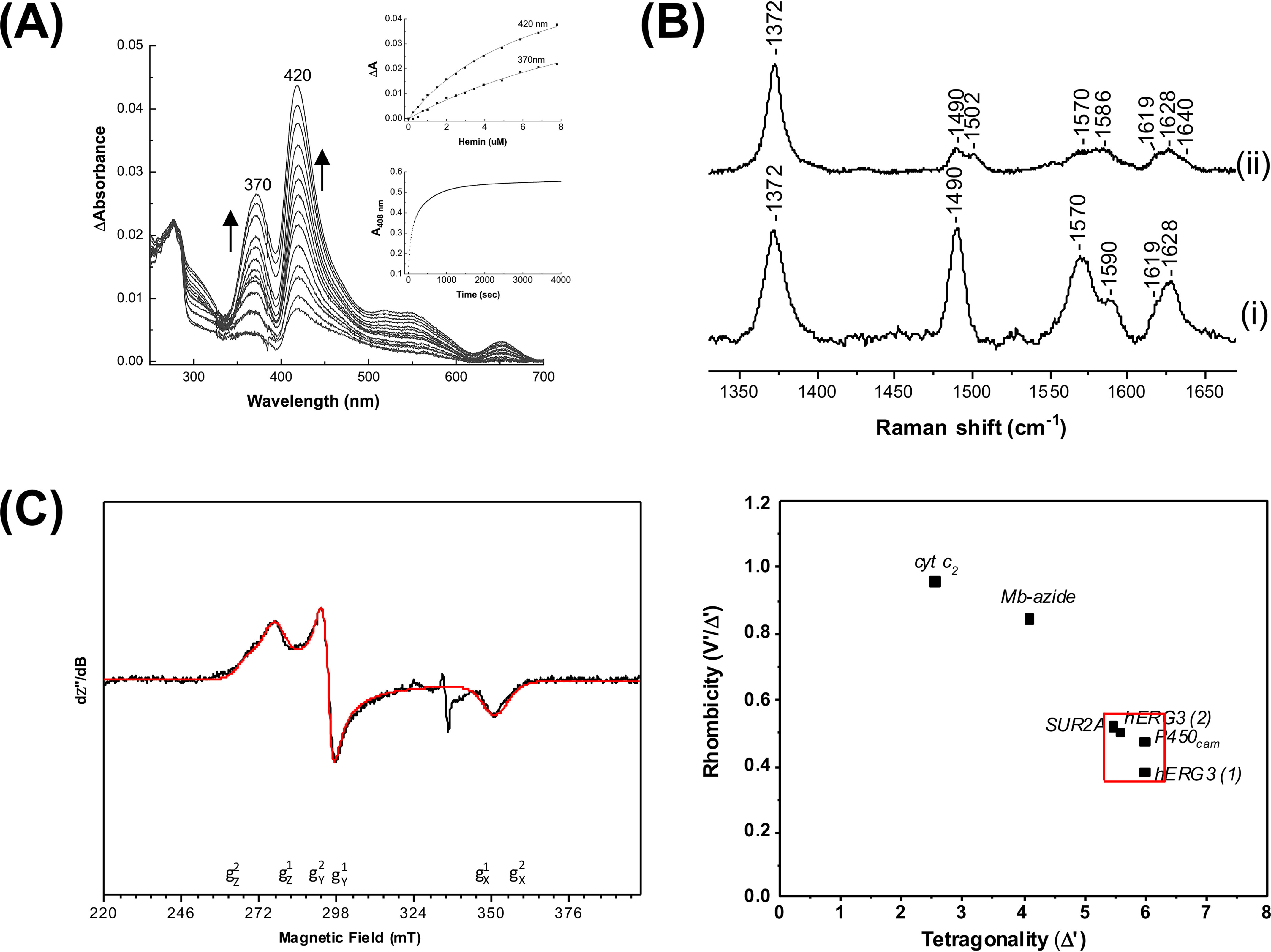
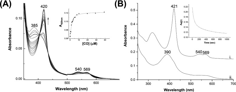
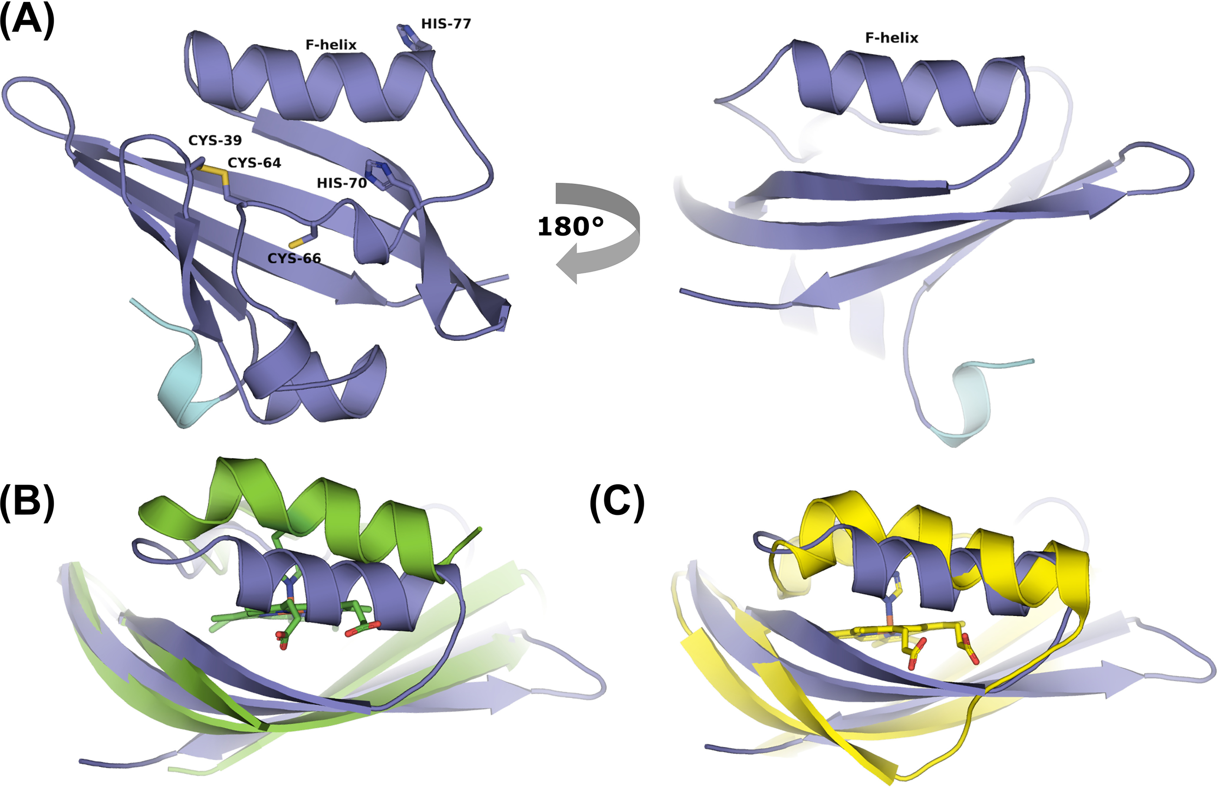
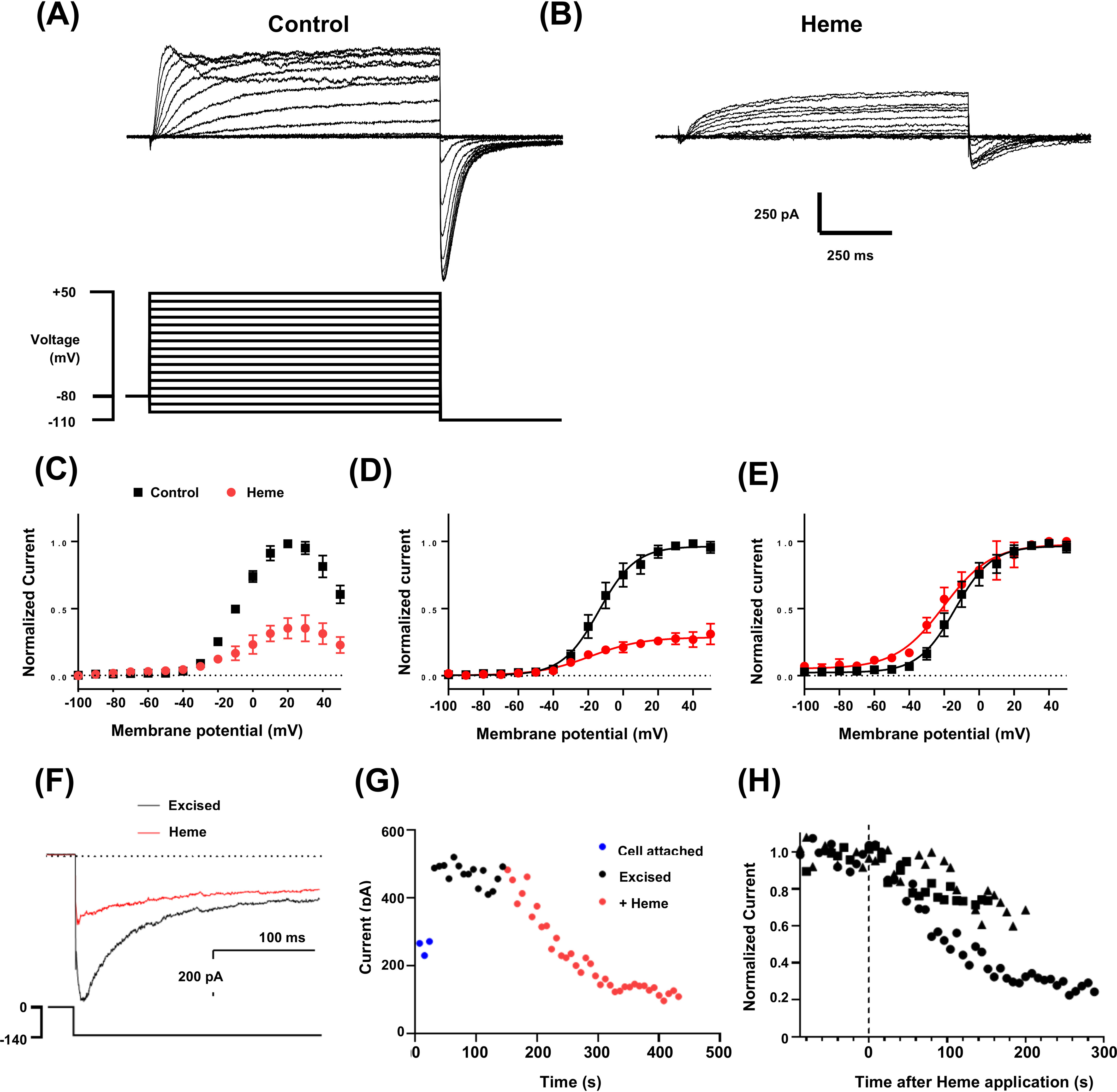
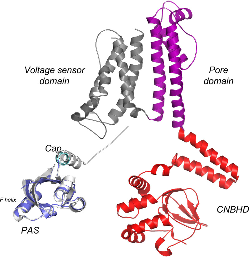
The EAG (ether-à-go-go) family of voltage-gated K+ channels are important regulators of neuronal and cardiac action potential firing (excitability) and have major roles in human diseases such as epilepsy, schizophrenia, cancer, and sudden cardiac death. A defining feature of EAG (Kv10-12) channels is a highly conserved domain on the N terminus, known as the eag domain, consisting of a Per-ARNT-Sim (PAS) domain capped by a short sequence containing an amphipathic helix (Cap domain). The PAS and Cap domains are both vital for the normal function of EAG channels. Using heme-affinity pulldown assays and proteomics of lysates from primary cortical neurons, we identified that an EAG channel, hERG3 (Kv11.3), binds to heme. In whole-cell electrophysiology experiments, we identified that heme inhibits hERG3 channel activity. In addition, we expressed the Cap and PAS domain of hERG3 in Escherichia coli and, using spectroscopy and kinetics, identified the PAS domain as the location for heme binding. The results identify heme as a regulator of hERG3 channel activity. These observations are discussed in the context of the emerging role for heme as a regulator of ion channel activity in cells.

Keywords: Cap domain; PAS domain; X-ray crystallography; hERG; hERG3; heme; heme regulation; ion channel; protein crystallization.


Conflict of interest statement

Conflict of interest—The authors declare that they have no conflicts of interest with the contents of this article.

Figures

Figure 1.
Figure 1.
Schematic of the hERG3 channel subunit. Left side, hERG, which is part of the EAG family of ion channels, has four subunits, each shown as a quadrant, that assemble to form a tetrameric structure as shown in the circular schematic on the left. Right side, each subunit contains a transmembrane region, as well as cytoplasmic N- and C-terminal regions. The transmembrane region contains voltage sensor (helices S1–S4, dark gray) and pore-forming (helices S5 and S6, magenta) domains inside the membrane bilayer. The C-terminal cytoplasmic region contains a cyclic nucleotide-binding homology domain (CNBHD, red), which is connected to the transmembrane region via a structured domain usually referred to as the C-linker. The N-terminal cytoplasmic region (∼400 residues) contains a region that is known as the eag domain (residues 1–135), which itself comprises a Cap domain (residues 1–26, light blue) and a PAS domain (residues 27–135, purple). This eag domain fragment (residues 1–135) has been expressed in this work and is referred to as hERG3-eag in this paper.
Figure 2.
Figure 2.
Analysis of heme binding to the hERG3-eag domain. A, difference spectra obtained on titration of the hERG3-eag domain with ferric heme; the arrows represent the directions of the absorbance changed with increasing heme concentration. Inset, top panel, hyperbolic fitting of the heme-binding data at both wavelength maxima to a 1:1 model for heme binding. Inset, bottom panel; absorbance changes at 408 nm on binding of the ferric hERG3-eag complex to apo-myoglobin. The data were fitted to the first order decay process, yielding kobs = 0.03 s−1. B, room temperature high-frequency resonance Raman spectra of free heme (panel (i)) and the ferric hERG3-eag–heme complex (panel (ii)). All spectra were collected with 413.1-nm laser excitation. C, left panel, X-band EPR spectrum (black trace) of the ferric hERG3-eag–heme complex in the low-spin region along with the simulated spectrum (red trace). The experimental conditions were as follows: microwave frequency, 9.38 GHz; microwave power, 0.064 mW; field modulation amplitude, 2 mT; field modulation frequency, 100 kHz; temperature, 15 K; [heme] = 100 μm, 5-fold excess of protein in 50 mm HEPES buffer, pH 7.5, 50 mm NaCl. The simulation parameters are as follows: species 1 (75%) g values (g strain) are gz1 = 2.42 (0.06), gy1 = 2.27 (0.00), and gx1 = 1.91 (0.04); species 2 (25%) g values (g strain) are gz2 = 2.50 (0,07), gy2 = 2.28 (0.00), and gx2 = 1.90 (0.06); Lorentzian linewidth full-width at half-maximum 4 mT. Right panel, Blumberg–Peisach correlation diagram showing EPR parameters plotted for various heme proteins.
Figure 3.
Figure 3.
A, spectrophotometric titration of the ferrous hERG3-eag–heme complex with CO. Inset, quadratic (Morrison) fitting to the binding curve to give Kd = 1.03 ± 0.37 μm. B, formation of a heme–NO–hERG3 complex (λmax = 390 nm) on dissociation of CO from the ferrous heme–hERG3 complex (3 μm, λmax = 421 nm) in the presence of NO. NO was formed from the NO releasing molecule, S-nitroso-N-acetyl penicillamine (see “Experimental procedures”). Inset, the 421-nm time course, fitted to a three-exponential process; using the dominant (50%) phase a rate constant for dissociation of CO, koff(CO), was determined (koff(CO) = 0.03 s−1).
Figure 4.
Figure 4.
A, cartoon representation of the hERG3-eag crystal structure showing the PAS (purple) and Cap (light blue) domains; the color scheme used is the same as that used in Fig. 1 for the PAS and Cap domains. Potential heme-binding residues are labeled. B and C, structural alignment of hERG3-eag with structures of heme-bound PAS domains in E. coli DOS (Protein Data Bank code 1V9Y, green in B) and FixL (Protein Data Bank code 1DP6, yellow in C). Movement of the F-helix in E. coli DOS and FixL allows binding of the heme.
Figure 5.
Figure 5.
hERG3 currents are inhibited by heme. A, representative whole-cell hERG3 currents (upper panel) elicited with voltage protocol (lower panel) consisting of 1-s test pulses from −100 to +50 mV in 10-mV increments and from a holding potential of −80 mV. Inward tail currents were measured at a potential of −110 mV. The start-start interval for the voltage protocol was 5 s. B, a family of hERG3 current traces from the same cell shown in A after superfusion of heme (500 nm). C, mean end-pulse current-voltage relationship with and without heme (500 nm) (n = 3). D and E, mean tail current (normalized to maximum control current in individual cells (D) or normalized to maximum current (E) in each recording solution) and plotted against test-pulse potential, with and without heme (500 nm) (n = 3). The data are fitted with Boltzmann functions (solid lines). Half-maximal activation (V0.5) and slope factor were −12.3 ± 4.7 mV and 10.7 ± 1.0 mV, respectively, before heme and −19.0 ± 4.4 mV and 14.1 ± 2.6 mV with heme (n = 3). F, representative traces of excised inside-out macro-patch recordings of hERG3 tail currents before and during application of heme (1 μm). Patches were excised into solutions containing 10 μm phosphoinositol 4,5-bisphosphate to attenuate current rundown. Intracellular and extracellular solutions contained equimolar K+ concentrations. Tail currents were measured at a potential of −140 mV and following 2-s test pulses to 0 mV (see voltage protocol in lower panel). Horizontal dotted lines in D–F indicate zero current. G, representative plot of changes in amplitude of the deactivating component of the tail current plotted against time. The time between traces was 8 s. H, scatter plot of hERG3 tail current amplitudes in three separate excised patches plotted against time after heme application. The time of heme application is indicated by the vertical dashed line.
Figure 6.
Figure 6.
Cryo-EM structure of the hERG1 (Kv11.1) channel (Protein Data Bank 5VA1), showing the CNBHD (red), the pore domain (magenta), and the voltage-sensing domain (dark gray). For direct comparison, the color schemes used for the CNBHD, pore, and voltage-sensing domains are the same as those shown schematically in Fig. 1. In addition, the PAS and Cap (in light gray) domains are also shown for hERG1, aligned with hERG3-eag crystal structure (PAS domain, in purple; Cap domain in light blue, color scheme as Fig. 1). Movements of the F-helix (labeled) or the Cap domain, induced by heme binding, might conceivably affect the conformations of the nearby CNBDH, pore, and voltage-sensing domains, which could provide a mechanism for channel regulation. Refer also to Fig. 1, which shows a schematic of the locations of each domain in relation to the overall channel structure. We have drawn cartoon schematics of heme-dependent regulation of several different ion channels previously (KATP, Slo1 (BK) and Kv1.4 channels (36)), and we envisage a similar mechanism of control here.

References

    1. Taylor B. L., and Zhulin I. B. (1999) PAS domains: internal sensors of oxygen, redox potential, and light. Microbiol. Mol. Rev. 63, 479–506 10.1128/MMBR.63.2.479-506.1999 - DOI - PMC - PubMed
    1. Henry J. T., and Crosson S. (2011) Ligand-binding PAS domains in a genomic, cellular, and structural context. Annu. Rev. Microbiol. 65, 261–286 10.1146/annurev-micro-121809-151631 - DOI - PMC - PubMed
    1. Möglich A., Ayers R. A., and Moffat K. (2009) Structure and signaling mechanism of Per–ARNT–Sim domains. Structure 17, 1282–1294 10.1016/j.str.2009.08.011 - DOI - PMC - PubMed
    1. Shimizu T., Lengalova A., Martínek V., and Martínková M. (2019) Heme: emergent roles of heme in signal transduction, functional regulation and as catalytic centres. Chem. Soc. Rev. 48, 5624–5657 10.1039/c9cs00268e - DOI - PubMed
    1. Shimizu T., Huang D., Yan F., Stranava M., Bartosova M., Fojtíková V., and Martínková M. (2015) Gaseous O2, NO, and CO in signal transduction: structure and function relationships of heme-based gas sensors and heme-redox sensors. Chem. Rev. 115, 6491–6533 10.1021/acs.chemrev.5b00018 - DOI - PubMed

Publication types