

Analytical Study of Front-End Circuits Coupled to Silicon Photomultipliers for Timing Performance Estimation under the Influence of Parasitic Components
- PMID: 32784392
- PMCID: PMC7472482
- DOI: 10.3390/s20164428
Analytical Study of Front-End Circuits Coupled to Silicon Photomultipliers for Timing Performance Estimation under the Influence of Parasitic Components
Abstract
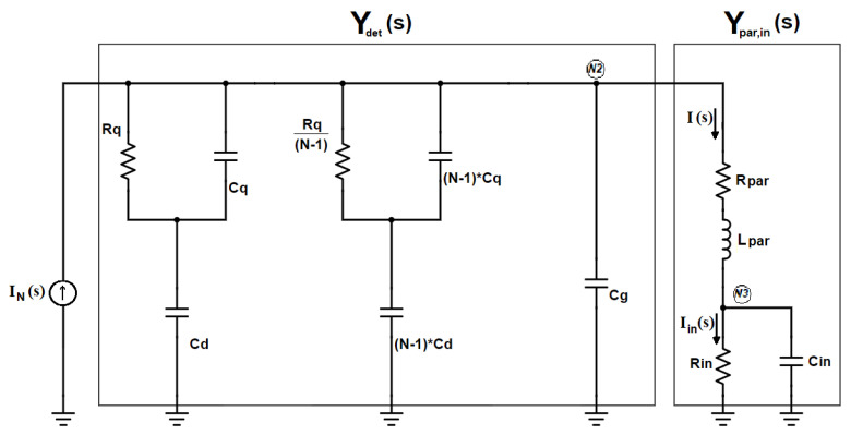
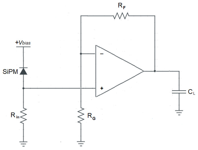
Full exploitation of the intrinsic fast timing capabilities of analog silicon photomultipliers (SiPMs) requires suitable front-end electronics. Even a parasitic inductance of a few nH, associated to the interconnections between the SiPM and the preamplifier, can significantly degrade the steepness of the detector response, thus compromising the timing accuracy. In this work, we propose a simple analytic expression for the single-photon response of a SiPM coupled to the front-end electronics, as a function of the main parameters of the detector and the preamplifier, taking into account the parasitic inductance. The model is useful to evaluate the influence of each parameter of the system on the slope of its response and to guide the designer in the definition of the architecture and the specifications for the front-end electronics. The results provided by the model have been successfully compared with experimental measurements from a front-end circuit with variable configuration based on a bipolar junction transistor (BJT), coupled to a 3 × 3 mm2 SiPM stimulated by a fast-pulsed laser source.
Keywords: front-end electronics; silicon photomultiplier; single-photon response; timing accuracy.
Conflict of interest statement
The authors declare no conflict of interest.
Figures


References
-
- Lamprou E., Aguilar A., Gonzalez-Montoro A., Monzo J., Canizares G., Vidal L.F., Hernandez L., Iranzo S., Marti R., Sanchez S., et al. Progress Report for an Accurate PET Detector Based on SiPMs and the TOFPET ASIC; Proceedings of the 2017 IEEE Nuclear Science Symposium and Medical Imaging Conference (NSS/MIC); Atlanta, GA, USA. 21–28 October 2017; pp. 1–3.
-
- Cozzi G., Busca P., Carminati M., Fiorini C., Montagnani G.L., Acerbi F., Gola A., Paternoster G., Piemonte C., Regazzoni V., et al. High-Resolution Gamma-Ray Spectroscopy With a SiPM-Based Detection Module for 1” and 2” LaBr3:Ce Readout. IEEE Trans. Nucl. Sci. 2018;65:645–655. doi: 10.1109/TNS.2017.2784238. - DOI
-
- Becker W. Advanced Time-Correlated Single Photon Counting Techniques. 1st ed. Springer; Berlin, Germany: 2005. Overview of Photon Counting Techniques.
-
- Adamo G., Busacca A. Time of Flight measurements via two LiDAR systems with SiPM and APD; Proceedings of the 2016 AEIT International Annual Conference (AEIT); Capri, Italy. 5–7 October 2016; pp. 1–5.
LinkOut - more resources
Full Text Sources
