. 2020 Aug 7;13(16):3484.
doi: 10.3390/ma13163484.

Ultra-Sensitive Affordable Cementitious Composite with High Mechanical and Microstructural Performances by Hybrid CNT/GNP

Affiliations

Ultra-Sensitive Affordable Cementitious Composite with High Mechanical and Microstructural Performances by Hybrid CNT/GNP

Mohammadmahdi Abedi et al. Materials (Basel). .

Abstract

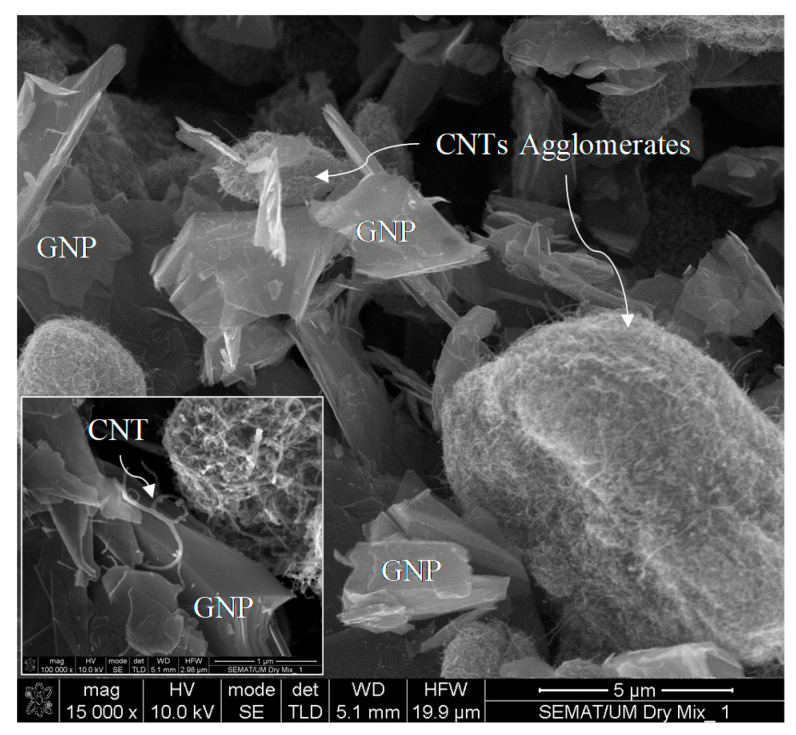
In this paper a hybrid combination of carbon nanotubes (CNTs) and graphene nanoplatelets (GNPs) was used for developing cementitious self-sensing composite with high mechanical, microstructural and durability performances. The mixture of these two nanoparticles with different 1D and 2D geometrical shapes can reduce the percolation threshold to a certain amount which can avoid agglomeration formation and also reinforce the microstructure due to percolation and electron quantum tunneling amplification. In this route, different concentrations of CNT + GNP were dispersed by Pluronic F-127 and tributyl phosphate (TBP) with 3 h sonication at 40 °C and incorporated into the cementitious mortar. Mechanical, microstructural, and durability of the reinforced mortar were investigated by various tests in different hydration periods (7, 28, and 90 days). Additionally, the piezoresistivity behavior of specimens was also evaluated by the four-probe method under flexural and compression cyclic loading. Results demonstrated that hybrid CNT + GNP can significantly improve mechanical and microstructural properties of cementitious composite by filler function, bridging cracks, and increasing hydration rate mechanisms. CNT + GNP intruded specimens also showed higher resistance against climatic cycle tests. Generally, the trend of all results demonstrates an optimal concentration of CNT (0.25%) + GNP (0.25%). Furthermore, increasing CNT + GNP concentration leads to sharp changes in electrical resistivity of reinforced specimens under small variation of strain achieving high gauge factor in both flexural and compression loading modes.

Keywords: cementitious composite; durability; hybrid CNT/GNP; mechanical; microstructural; piezoresistivity; self-sensing.


Conflict of interest statement

The authors declare no conflict of interest for this research work.

Figures

Figure 1
Figure 1
Morphology of carbon nanotubes (CNTs) and graphene nanoplatelets (GNPs) dry mixtures.
Figure 2
Figure 2
Chemical structure of: (a) Pluronic F-127, (b) tributyl phosphate 97% [32].
Figure 3
Figure 3
Size curves of cement and sand.
Figure 4
Figure 4
CNT and GNP Raman analysis results.
Figure 5
Figure 5
Representation of the geometrical parameters and resistivity measurement principle.
Figure 6
Figure 6
Freeze–thaw temperature cycle.
Figure 7
Figure 7
(a) Flexural and (b) compressive strengths of CNT + GNP incorporating cementitious composites at different curing time.
Figure 8
Figure 8
Normalized compressive (Comp) and flexural (Flex) strength of plain and CNMs reinforced mortar for different curing times.
Figure 9
Figure 9
Plain and CNMs reinforced rupture modulus in different hydration periods: (a) flexural, (b) compressive.
Figure 9
Figure 9
Plain and CNMs reinforced rupture modulus in different hydration periods: (a) flexural, (b) compressive.
Figure 10
Figure 10
Images of specimens after tests: (a) specimen GC (0.5%) after flexural test, (b) specimen GC (0.5%) after compression test.
Figure 11
Figure 11
Scanning electron microscopy (SEM) morphology of CNT + GNP specimen after mechanical strength test. (a) GC (0.5%), (b) GC (0.7%).
Figure 12
Figure 12
Apparent porosity of nano intruded cement mortars.
Figure 13
Figure 13
Dry bulk density of nano-intruded cement mortars.
Figure 14
Figure 14
The weight loss rate of cementitious composites in different freeze–thaw cycles.
Figure 15
Figure 15
Relative dynamic elasticity modulus of CNT + GNP intruded cement mortar after 180 freeze-thaw cycles.
Figure 16
Figure 16
The electrical resistance of reinforced cementitious composite by different CNT + GNP concentrations and curing time.
Figure 17
Figure 17
Buried GNPs and CNTs among of the hydration products.
Figure 18
Figure 18
SEM image of incorporated CNT + GNP into the cement mortar.
Figure 19
Figure 19
Schematic of tunneling effect for CNT/CNT and CNT/GNP cases.
Figure 20
Figure 20
The fractional change in resistivity together with cyclic compression response for reinforced cementitious composite by different CNT + GNP concentration.
Figure 21
Figure 21
The fractional change in resistivity together with axial strain under cyclic compression loading. (a) GC (0.1%); (b) GC (0.3%); (c) GC (0.5%); (d) GC (0.7%); (e) GC (1.0%.
Figure 21
Figure 21
The fractional change in resistivity together with axial strain under cyclic compression loading. (a) GC (0.1%); (b) GC (0.3%); (c) GC (0.5%); (d) GC (0.7%); (e) GC (1.0%.
Figure 22
Figure 22
The ratio of rupture compressive modulus (Ecr) to compressive modulus at 10 KN loading (EC10).
Figure 23
Figure 23
Variation of strain with the fractional change in resistivity for CNT + GNP reinforced specimens.
Figure 24
Figure 24
The fractional change in resistivity together with the cyclic flexural response for reinforced cementitious composite by different CNT + GNP concentrations.
Figure 25
Figure 25
The fractional change in resistivity together with axial strain under cyclic compression loading. (a) GC (0.1%); (b) GC (0.3%); (c) GC (0.5%); (d) GC (0.7%); (e) GC (1.0%.
Figure 25
Figure 25
The fractional change in resistivity together with axial strain under cyclic compression loading. (a) GC (0.1%); (b) GC (0.3%); (c) GC (0.5%); (d) GC (0.7%); (e) GC (1.0%.
Figure 26
Figure 26
The ratio of flexural modulus at rupture (EFr) to flexural modulus at 500 N loading (EF500).
Figure 27
Figure 27
Variation of strain with the fractional change in resistivity for CNT+GNP reinforced specimens under flexural cyclic loading.
Figure 28
Figure 28
Variation of gauge factors in flexural and compression loading.

References

    1. Ozbulut O.E., Jiang Z., Harris D.K. Exploring scalable fabrication of self-sensing cementitious composites with graphene nanoplatelets. Smart Mater. Struct. 2018;27:115029. doi: 10.1088/1361-665X/aae623. - DOI
    1. Aggelis D.G., Alver N., Chai H.K. Health Monitoring of Civil Infrastructure and Materials. Sci. World J. 2014;2014:2. doi: 10.1155/2014/435238. - DOI - PMC - PubMed
    1. Le J.-L., Du H., Pang S.D. Use of 2D Graphene Nanoplatelets (GNP) in cement composites for structural health evaluation. Compos. Part B Eng. 2014;67:555–563. doi: 10.1016/j.compositesb.2014.08.005. - DOI
    1. Dong W., Li W., Shen L., Sun Z., Sheng D. Piezoresistivity of smart carbon nanotubes (CNTs) reinforced cementitious composite under integrated cyclic compression and impact. Compos. Struct. 2020;241:112106. doi: 10.1016/j.compstruct.2020.112106. - DOI
    1. Nazerigivi A., Najigivi A. Study on mechanical properties of ternary blended concrete containing two different sizes of nano-SiO2. Compos. Part B Eng. 2019;167:20–24. doi: 10.1016/j.compositesb.2018.11.136. - DOI

LinkOut - more resources