. 2020 Sep 1;117(35):21138-21146.
doi: 10.1073/pnas.2007395117. Epub 2020 Aug 19.

Ultraflexible organic light-emitting diodes for optogenetic nerve stimulation

Affiliations

Ultraflexible organic light-emitting diodes for optogenetic nerve stimulation

Dongmin Kim et al. Proc Natl Acad Sci U S A. .

Abstract

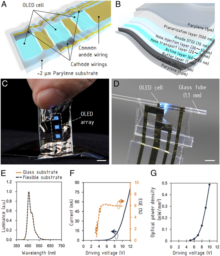
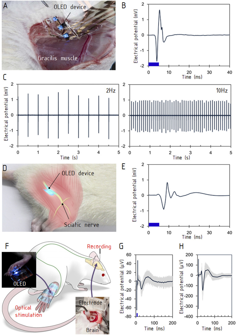
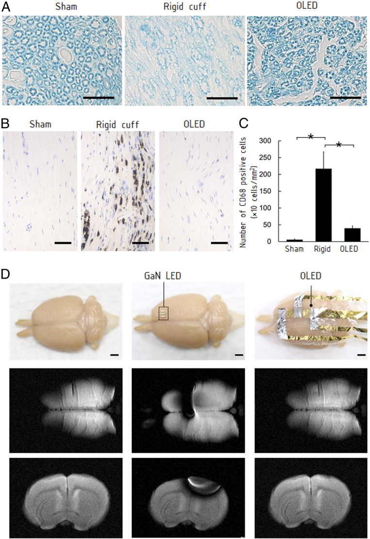
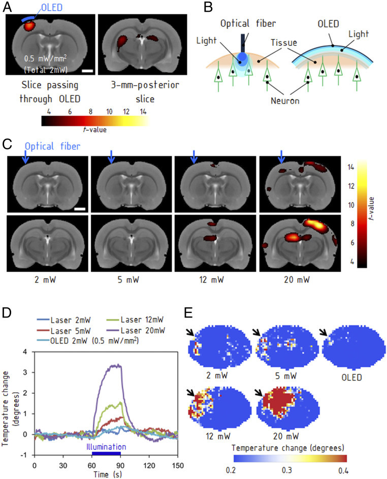
Organic electronic devices implemented on flexible thin films are attracting increased attention for biomedical applications because they possess extraordinary conformity to curved surfaces. A neuronal device equipped with an organic light-emitting diode (OLED), used in combination with animals that are genetically engineered to include a light-gated ion channel, would enable cell type-specific stimulation to neurons as well as conformal contact to brain tissue and peripheral soft tissue. This potential application of the OLEDs requires strong luminescence, well over the neuronal excitation threshold in addition to flexibility. Compatibility with neuroimaging techniques such as MRI provides a method to investigate the evoked activities in the whole brain. Here, we developed an ultrathin, flexible, MRI-compatible OLED device and demonstrated the activation of channelrhodopsin-2-expressing neurons in animals. Optical stimulation from the OLED attached to nerve fibers induced contractions in the innervated muscles. Mechanical damage to the tissues was significantly reduced because of the flexibility. Owing to the MRI compatibility, neuronal activities induced by direct optical stimulation of the brain were visualized using MRI. The OLED provides an optical interface for modulating the activity of soft neuronal tissues.

Keywords: flexible sensor; optogenetic; organic electronics.


Conflict of interest statement

The authors declare no competing interest.

Figures

Fig. 1.
Fig. 1.
Structure and characteristics of ultraflexible OLED device. (A) Structure of the OLED device with three emission cells and wirings. (B) Cross-sectional view of the emission cell. (C) Photograph of the OLED detached from the supporting glass substrate. (Scale bars, 4 mm.) (D) Light emission from the bent OLED. (Scale bar, 2 mm.) (E) The electroluminescence spectra of the OLED. a.u., arbitrary units. (F) The I-V characteristics and the external quantum efficiency of the OLED. (G) The optical-power density against the driving voltage.
Fig. 2.
Fig. 2.
Stimulations of motor and sensory systems. (A) The OLED was attached to a surface of gracilis muscle (Materials and Methods). (B) The evoked electromyogram. The stimulation frequency was 10 Hz, and the data were averaged over 10 stimulations. (C) The evoked electromyograms at 2 and 10 Hz. (D) The OLED was placed on the exposed sciatic nerve of the hindlimb. (E) The evoked electromyogram at the gastrocnemius muscle. The stimulation frequency was 10 Hz, and the data were averaged over 10 stimulations. (F) The experimental setup for stimulating sensory neurons in the hindlimb and recording the somatosensory evoked potential in the brain. The lower right photograph shows the needle electrode inserted into the primary somatosensory cortex (S1) contralateral to the stimulated hindlimb. The upper left photograph shows the OLED attached to the hindlimb. (G) Electrical potentials evoked by optical stimulations. The first negative peak occurred ∼25 ms after stimulation, and the peak pair at <10 ms was an artifact caused by the stimulation. (H) Evoked potentials by electrical stimulations to the hindlimb. The stimulus intensity and duration were 0.7 mA and 300 μs, respectively. The blue bars in B, E, and G show the durations of optical stimulations (5 ms).
Fig. 3.
Fig. 3.
Characterization of OLED attached on neuronal tissues. (A) Histological sections of sciatic nerves with a cuff representing a rigid optical emitter and the OLED attached around the nerve for 10 d (Materials and Methods). The transverse section stained with Luxol fast blue exhibits significant morphological change of the myelin sheath when the rigid cuff was attached. There was no clear difference between the nerve with the OLED and the sham-operated nerve. (Scale bars, 20 μm.) (B) CD68 immunostaining on the longitudinal sections. The nerve with the rigid cuff exhibited overexpressed CD68, suggesting damage to the nerve. The nerve with the OLED did not exhibit overexpression. (Scale bar, 50 μm.) (C) The number of CD68-positive cells per unit area (cells per square millimeter) in each group (sham, rigid cuff implantation, and OLED implantation). Data are presented as means ± SEM. Asterisk denotes statistically significant differences across the groups (one-way ANOVA, F = 7.32, P = 0.02; Tukey–Kramer HSD test, P < 0.05). (D) MRI of a perfusion-fixed rat brain and the brain with attached conventional GaN LED and OLED. (Scale bar, 2 mm.) While the GaN LED caused an artifact, the influence of the OLED was negligible.
Fig. 4.
Fig. 4.
MRI of brain activities evoked by optical stimulations. (A) The left map shows activation in the sensorimotor cortex, which was located immediately below the OLED emission area (Materials and Methods). The right map shows the induced activation in the thalamus 3 mm posterior to the stimulated area. (Scale bars, 2 mm.) (B) Difference between the OLED providing an area light source and an optical fiber providing a point light source. (C) fMRI obtained with stimulations from a fiber-coupled laser with light powers ranging from 2 to 20 mW. BOLD responses were evoked at 12 mW and higher. The images in the bottom row are at 3 mm posterior from the images in the top row. (Scale bars, 2 mm.) (D) Rise in temperature caused by illumination with the OLED and fiber-coupled laser. The measurements were performed on a rat brain with a craniotomy of 4 mm × 4 mm using a thermocouple. (E) Thermographs for each light power. The illumination using the optical fiber generated a hot spot, whereas the OLED caused a much smaller thermal effect. The measurements were performed using an extracted brain.

References

    1. Someya T., Bao Z., Malliaras G. G., The rise of plastic bioelectronics. Nature 540, 379–385 (2016). - PubMed
    1. Kaltenbrunner M. et al., An ultra-lightweight design for imperceptible plastic electronics. Nature 499, 458–463 (2013). - PubMed
    1. Wang S. et al., Skin electronics from scalable fabrication of an intrinsically stretchable transistor array. Nature 555, 83–88 (2018). - PubMed
    1. Khodagholy D. et al., In vivo recordings of brain activity using organic transistors. Nat. Commun. 4, 1575 (2013). - PMC - PubMed
    1. Leleux P. et al., Organic electrochemical transistors for clinical applications. Adv. Healthc. Mater. 4, 142–147 (2015). - PubMed

Publication types

LinkOut - more resources