. 2020 Aug 14;20(16):4563.
doi: 10.3390/s20164563.

Compensation System for Biomagnetic Measurements with Optically Pumped Magnetometers inside a Magnetically Shielded Room

Affiliations

Compensation System for Biomagnetic Measurements with Optically Pumped Magnetometers inside a Magnetically Shielded Room

Anna Jodko-Władzińska et al. Sensors (Basel). .

Abstract

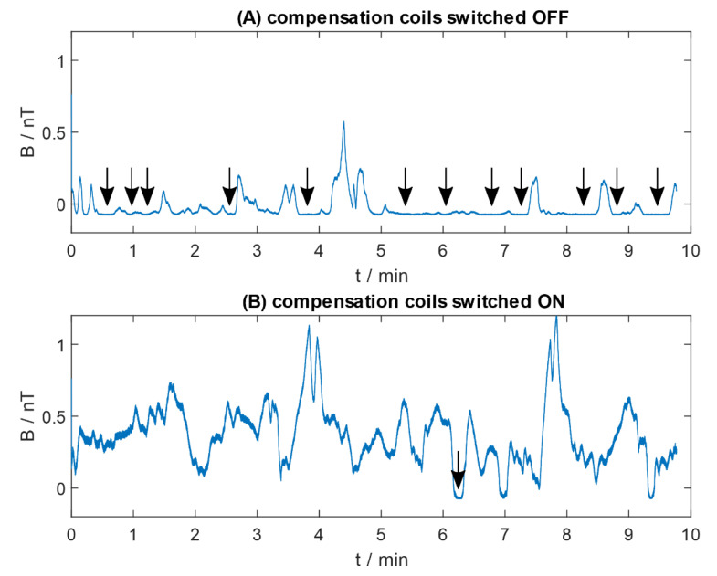
Magnetography with superconducting quantum interference device (SQUID) sensor arrays is a well-established technique for measuring subtle magnetic fields generated by physiological phenomena in the human body. Unfortunately, the SQUID-based systems have some limitations related to the need to cool them down with liquid helium. The room-temperature alternatives for SQUIDs are optically pumped magnetometers (OPM) operating in spin exchange relaxation-free (SERF) regime, which require a very low ambient magnetic field. The most common two-layer magnetically shielded rooms (MSR) with residual magnetic field of 50 nT may not be sufficiently magnetically attenuated and additional compensation of external magnetic field is required. A cost-efficient compensation system based on square Helmholtz coils was designed and successfully used for preliminary measurements with commercially available zero-field OPM. The presented setup can reduce the static ambient magnetic field inside a magnetically shielded room, which improves the usability of OPMs by providing a proper environment for them to operate, independent of initial conditions in MSR.

Keywords: Helmholtz coils; biomagnetism; magnetically shielded room; optically pumped magnetometer.


Conflict of interest statement

The authors declare no conflict of interest.

Figures

Figure 1
Figure 1
Conceptual transfer curve of the zero-field optically pumped magnetometer electronic module output: (A) under ideal conditions; (B) with the presence of the bias magnetic field. In (B), signal saturation is visible.
Figure 2
Figure 2
CAD model of the designed compensation system, based on square Helmholtz coils; dimensions in millimeters. Figure created using Inventor® CAD software (Autodesk, Inc., San Rafael, CA, USA [53]).
Figure 3
Figure 3
Wooden Helmholtz coils setup installed in a two-layer magnetically shielded room (Vacoshield Advanced, Vacuumschmelze GmbH & Co. KG, Hanau, Germany) at Warsaw University of Technology, Faculty of Mechatronics.
Figure 4
Figure 4
Electrical circuit of the current source for one pair of compensation coils, where BU-SMA-G—a female SMA connector for voltage control signal, JP2—jumper to choose the method of controlling the current source (manually via potentiometer or voltage control, e.g., via acquisition card).
Figure 5
Figure 5
Current supplying the coils vs. the magnetic field generated in the central volume; blue plot—measurements in the positive sensor direction, red plot—measurements in the negative direction, where positive relates to the same direction as the magnetic field vector and negative relates to the opposite. For both series of data, linear fit was calculated, as well as 95% prediction interval. Measurement directions (x, y, z) correspond to the coordinate system in Figure 2.
Figure 6
Figure 6
Residual magnetic field measured with QuSpin zero field magnetometer inside two-layer magnetically shielded room with the additional compensation coils: (A) switched off; (B) switched on. Arrows indicate the areas of signal saturation.
Figure 7
Figure 7
Distribution of magnetic induction of residual magnetic field measured with QuSpin zero field magnetometer inside the two-layer magnetically shielded room with the additional compensation coils switched off (blue) and switched on (red). The bin width was set to 0.02 nT, the number of bins: 66 (red) and 43 (blue). The skewed histogram of the measurement taken with the coils switched off (blue) with extreme dominant number of samples of magnetic induction in the range from −0.08 to −0.06 nT corresponds to the signal saturation.

References

    1. Williamson S.J., Kaufman L. Biomagnetism. J. Mag. Mag. Mater. 1981;22:129–201. doi: 10.1016/0304-8853(81)90078-0. - DOI
    1. Baule G., McFee R. Detection of the magnetic field of the heart. Am. Heart J. 1963;66:95–96. doi: 10.1016/0002-8703(63)90075-9. - DOI - PubMed
    1. Cohen D. Magnetoencephalography: Evidence of magnetic fields produced by alpha-rhythm currents. Science. 1968;161:784–786. doi: 10.1126/science.161.3843.784. - DOI - PubMed
    1. Bauman J.H., Harris J.W. Estimation of hepatic iron stores by in vivo measurement of magnetic susceptibility. J. Lab. Clin. Med. 1967;70:246–257. - PubMed
    1. Stroink G., Hailer B., Van Leeuwen P. Cardiomagnetism. In: Andrä W., Nowak H., editors. Magnetism in Medicine: A Handbook. 2nd ed. Wiley-VCH Verlag GmbH & Co. KGaA; Weinheim, Germany: 2007. pp. 183–209.