. 2020 Aug 26;11(1):4276.
doi: 10.1038/s41467-020-17861-7.

A spike-timing-dependent plasticity rule for dendritic spines

Affiliations

A spike-timing-dependent plasticity rule for dendritic spines

Sabrina Tazerart et al. Nat Commun. .

Abstract

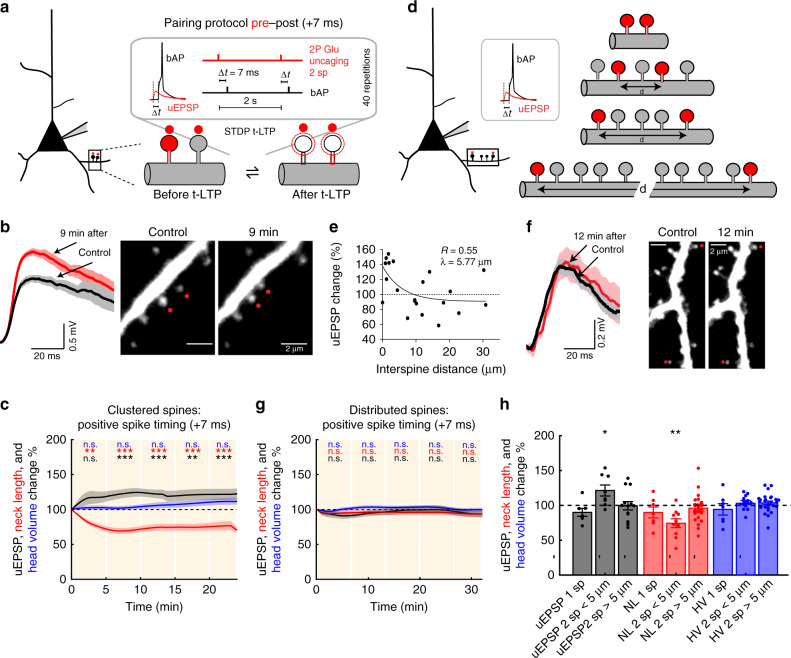
The structural organization of excitatory inputs supporting spike-timing-dependent plasticity (STDP) remains unknown. We performed a spine STDP protocol using two-photon (2P) glutamate uncaging (pre) paired with postsynaptic spikes (post) in layer 5 pyramidal neurons from juvenile mice. Here we report that pre-post pairings that trigger timing-dependent LTP (t-LTP) produce shrinkage of the activated spine neck and increase in synaptic strength; and post-pre pairings that trigger timing-dependent LTD (t-LTD) decrease synaptic strength without affecting spine shape. Furthermore, the induction of t-LTP with 2P glutamate uncaging in clustered spines (<5 μm apart) enhances LTP through a NMDA receptor-mediated spine calcium accumulation and actin polymerization-dependent neck shrinkage, whereas t-LTD was dependent on NMDA receptors and disrupted by the activation of clustered spines but recovered when separated by >40 μm. These results indicate that synaptic cooperativity disrupts t-LTD and extends the temporal window for the induction of t-LTP, leading to STDP only encompassing LTP.


Conflict of interest statement

The authors declare no competing interests.

Figures

Fig. 1
Fig. 1. Induction of t-LTP in single dendritic spines.
a Experimental protocol for t-LTP induction in single dendritic spines (sp). b Representative experiment where a spine was activated with t-LTP pre–post pairing protocol of +13 ms. Traces correspond to average of ten uEPSPs recorded in the soma and generated by 2P uncaging before (control, black trace) and after t-LTP induction (red trace) over the indicated spine (red dot). c Time course of uEPSP amplitude, neck length, and spine head volume (P < 0.001, P < 0.001, and P = 0.25, respectively, n = 9 spines, one-way repeated-measures ANOVA) following STDP induction with pre–post timing of +13 ms. n.s. not significant; *P < 0.05; ***P < 0.001, post hoc Dunnet’s test. d Changes in uEPSP amplitude, neck length, and head volume of the activated spine 15–25 min after t-LTP induction with a pre–post timing of +13 ms (uEPSP = 121.00 ± 6.98%, P = 0.039, neck length = 71.88 ± 8.29%, P = 0.019, spine head volume = 109.63 ± 8.84%, P = 0.38; n = 9 spines, two-sided Wilcoxon test; *P < 0.05). e Time course of uEPSP amplitude, neck length, and spine head volume (P = 0.45, 0.09, and 0.36 respectively, n = 8 spines, one-way repeated-measures ANOVA) changes following STDP induction with pre–post timing of +7 ms. n.s. not significant, post hoc Dunnet’s test. f Changes in uEPSP amplitude, neck length, and head volume of the activated spine 15–25 min after t-LTP induction with a pre–post timing of +7 ms (uEPSP = 90.06 ± 5.00%, P = 0.15; neck length = 92.10 ± 7.15%, P = 0.38; spine head volume = 95.67 ± 7.25%, P = 0.84; n = 8 spines, two-sided Wilcoxon test). Shaded area and error bars represent SEM and Time 0 represents the end of the STDP induction protocol. Lines, bars, and dots in cf: uEPSP = black, neck length = red, and head volume = blue.
Fig. 2
Fig. 2. Induction of t-LTD in single dendritic spines.
a Experimental protocol for t-LTD induction in single dendritic spines. b Representative experiment where a spine was activated with t-LTD post–pre pairing of −15 ms. Traces correspond to average of 10 uEPSPs recorded at the soma and generated by 2P uncaging before (control, black trace) and after t-LTD induction (red trace) over indicated spine (red dot). c Time course of uEPSP amplitude, neck length, and spine head volume (P < 0.001, P = 0.45, and P = 0.97, respectively, n = 7 spines, one-way repeated-measures ANOVA) changes following STDP induction (−15 ms). n.s. not significant; ***P < 0.001, post hoc Dunnet’s test. d Changes in uEPSP amplitude, neck length, and head size of the activated spine 15–25 min after t-LTD induction (−15 ms) (uEPSP = 75.83 ± 5.14%, P = 0.016; neck length = 98.86 ± 7.51%, P = 0.81; spine head volume = 103.06 ± 2.78%, P = 0.58, n = 7 spines, two-sided Wilcoxon test; *P < 0.05). e Time course of uEPSP amplitude, neck length, and spine head volume (P = 0.28, 0.71, and 0.66, respectively, n = 7 spines, one-way repeated-measures ANOVA) changes following STDP induction with a post–pre timing of −23 ms. n.s. not significant, post hoc Dunnet’s test. f Changes in uEPSP amplitude, neck length, and head volume of the activated spine 15–25 min after t-LTD induction (−23 ms) (uEPSP = 89.01 ± 10.73%, P = 0.46; neck length = 88.05 ± 11.35%, P = 0.38; spine head volume = 100.94 ± 7.93%, P = 0.81, n = 7 spines, two-sided Wilcoxon test). g STDP learning rule for single dendritic spines: uEPSP amplitude, neck length, and head volume changes as a function of spike timing (+13 ms: P = 0.039 and 0.019 for uEPSP and neck length, respectively, n = 9 spines; −15 ms: P < 0.001 for uEPSP, n = 7 spines, two-sided Wilcoxon test; *P < 0.05). h Diagram showing uEPSP amplitude and spine neck morphological changes after STDP induction. Shaded area and error bars represent SEM. Lines, bars, and dots in cg: uEPSP = black, neck length = red, and head volume = blue.
Fig. 3
Fig. 3. Induction of t-LTP in clustered and distributed dendritic spines.
a Experimental protocol for t-LTP induction in two clustered dendritic spines (<5 µm apart). b Representative experiment for t-LTP induction (pre–post pairing of +7 ms) in two clustered spines. Traces correspond to the average of 10 uEPSPs recorded in the soma and generated by 2P uncaging before (control, black trace) and after t-LTP induction (red trace) over indicated spines (red dots). c Time course of uEPSP amplitude, neck length, and spine head volume (P < 0.001, P < 0.001, P = 0.47, respectively, n = 8 spine pairs, one-way repeated-measures ANOVA) changes following STDP induction (+7 ms) in two clustered spines. n.s. not significant; **P < 0.01, ***P < 0.001, post hoc Dunnet’s test. d Experimental protocol for t-LTP induction (+7 ms) in two distributed spines (>5 μm apart). e t-LTP induction (+7 ms) in two nearly simultaneously activated spines is dependent on interspine distance. The estimated value of λ represents the boundary between clustered and distributed spines. f Same as b, but for two distributed spines (>5 μm apart). g Time course of uEPSP amplitude, neck length and spine head volume (P = 0.45, 0.07, and 0.64, respectively, one-way repeated-measures ANOVA) following STDP induction (+7 ms) in two distributed spines. n.s. not significant, post hoc Dunnet’s test. h Changes in uEPSP amplitude, neck length, and head volume for individual (1 sp), clustered (<5 μm) and distributed (>5 μm) spines (2 sp) 15–25 min after t-LTP induction (+7 ms) (clustered: uEPSP = 121.73 ± 7.92%, P = 0.02, n = 8 spine pairs; neck length = 74.33 ± 6.35%, P = 0.0039; spine head volume = 107.92 ± 3.69%, P = 0.039; distributed: uEPSP = 100.03 ± 6.18%, P = 0.95, n = 12 spine pairs; neck length = 95.88 ± 4.87%, P = 0.28; spine head volume = 103.71 ± 2.61%, P = 0.11, two-sided Wilcoxon test; *P < 0.05, **P < 0.01). Shaded area and error bars represent SEM. Lines, bars, and dots in c, g, h: uEPSP = black, neck length (NL) = red, and head volume (HV) = blue.
Fig. 4
Fig. 4. Molecular mechanisms responsible for the induction of t-LTP.
a Experimental design for t-LTP induction in two clustered spines (<5 µm) with PEP1-TGL (200 µM) inside the pipette. b Representative experiment where two clustered spines were activated with t-LTP pre–post pairing of +7 ms. Traces correspond to an average of 10 uEPSPs recorded in the soma and generated by 2P uncaging before (control, black trace) and after the induction of t-LTP with PEP1-TGL (red trace) over the indicated spines (red dots). c Time course of uEPSP amplitude, neck length, and spine head volume (P = 0.75, P < 0.001, P = 0.96, respectively, n = 5 spine pairs, one-way repeated-measures ANOVA) changes following STDP induction (+7 ms) in clustered spines with PEP1-TGL. n.s. not significant; **P < 0.01, post hoc Dunnet’s test. d Changes in uEPSP amplitude, neck length, and head volume of activated clustered spines 15–25 min after t-LTP induction (+7 ms) in control conditions (Cont) and with PEP1-TGL (PEP1-TGL: uEPSP = 94.82 ± 14.82%, P = 0.81; neck length = 79.71 ± 4.32%, P = 0.0078; spine head volume = 100.08 ± 3.23%, P = 1, n = 5 spine pairs, two-sided Wilcoxon test; *P < 0.05, **P < 0.01). e Experimental design for t-LTP induction in two clustered spines (<5 µm) with Latrunculin-A (Lat-A, 100 nM). f Same as b, but with Lat-A. g Time course of uEPSP amplitude, neck length, and spine head volume (P < 0.001, P = 0.35, P = 0.72, respectively, n = 9 spine pairs, one-way repeated-measures ANOVA) changes following STDP induction (+7 ms) in clustered spines with Lat-A. n.s. not significant; **P < 0.01, post hoc Dunnet’s test. h Changes in uEPSP amplitude, neck length, and head volume of the activated clustered spines 15–25 min after t-LTP induction (+7 ms) in control conditions (Cont) and with Lat-A (Lat-A: uEPSP = 69.55 ± 7.13%, P = 0.008; neck length = 93.04 ± 6.01%, P = 0.32; spine head volume = 99.80 ± 4.33%, P = 0.95, n = 9 spine pairs, two-sided Wilcoxon test; *P < 0.05, **P < 0.01). Shaded area and error bars represent SEM. Lines, bars, and dots in c, d, g, h: uEPSP = black, neck length (NL) = red, and head volume (HV) = blue.
Fig. 5
Fig. 5. Induction of t-LTD in clustered and distributed dendritic spines.
Experimental protocol for t-LTD induction in a two clustered (<40 µm) or b two distributed spines (>40 μm apart). c Representative experiment where two clustered spines were activated with a t-LTD post–pre pairing of −15 ms. Traces correspond to an average of 10 uEPSPs recorded in the soma and generated by 2P uncaging before (control, black trace) and after t-LTD induction (red trace) over the indicated spines (red dots) d Time course of uEPSP amplitude, the neck length and spine head volume (P = 0.24, 0.47, and 0.32, respectively, n = 12 spine pairs, one-way repeated-measures ANOVA) of the activated clustered spines after t-LTD induction (−15 ms). n.s. not significant; *P < 0.05, post hoc Dunnet’s test. e t-LTD recovery is dependent on interspine distance. f Same as c, but for distributes spines (>40 μm apart). Insets shows a low magnification image of the recorded neuron with the marked location of the selected spines. g Time course of uEPSP amplitude, the neck length and spine head volume (P < 0.001, P = 0.67, and P = 0.56, respectively, n = 8 spine pairs, one-way repeated-measures ANOVA) of the activated distributed spines after the induction of t-LTD (−15 ms). n.s. not significant; *P < 0.05, **P < 0.01 and ***P < 0.001, and post hoc Dunnet’s test. h Changes in uEPSP amplitude, neck length, and head volume of individual (1 sp), clustered (2 sp < 40 µm) and distributed spines (2 sp > 40 µm) 15–25 min after the t-LTD induction (−1 ms) (clustered: uEPSP = 95.65 ± 6.42%, P = 0.62; neck length = 88.07 ± 5.58%, P = 0.04; spine head volume = 102.08 ± 8.94%, P = 0.38, n = 12 spine pairs; distributed: uEPSP = 84.40 ± 3.12%, P = 0.016; neck length = 98.78 ± 3.12%, P = 0.68; spine head volume = 105.84 ± 5.56%, P = 0.50, n = 8 spine pairs, two-sided Wilcoxon test; *P < 0.05). Shaded area and error bars represent SEM. Lines, bars, and dots in d, g, h: uEPSP = black, neck length (NL) = red, and head volume (HV) = blue.
Fig. 6
Fig. 6. Calcium dynamics in single and two clustered spines during t-LTP induction.
a Single 2P images of a spine and dendrite from a L5 pyramidal neuron loaded with Alexa Fluor 594 (shown in a) and Fluo-4 (shown in b). Red ellipses and blue polygons indicate the ROIs selected for analysis. b Two-photon calcium signal images before (left panels) and after (right panels) a +7 ms pre–post pairing. The 1st, 2nd, and 40th repetitions of the pairing protocol are shown. Change in calcium fluorescence from baseline (ΔF) is color coded. Only positive changes in fluorescence are shown. White ellipses and polygons indicate the ROIs selected for analysis. c Average and individual ΔGR traces from spine ROIs for each of the 40 repetitions during the experiment depicted in a, b. Dotted line is the time when pairing occurred. d, e Population averages of ΔGR measured in d spines and e dendrites before the pairing performed in one spine (left panels; P = 0.28 and 0.13, respectively, n = 7 spines and dendrites, from six neurons, and four mice) and two spines (middle panels; P < 0.0001 and P = 0.006, respectively, n = 12 spines and 6 dendrites, from four neurons, and four mice, one-way repeated-measures ANOVA). Right panels show ΔGR population averages for one (black lines) and two spines (green lines). f, g As in a, b, but for two clustered spines. h Average and individual ΔGR traces from ROIs (sp1 versus sp2) from each of the 40 repetitions during the pre–post pairing in the experiment depicted in f, g. Dotted line is the time when pairing occurred. i, j Population averages of ΔGR measured in i spines and j dendrites after the pairing in one spine (left panels; P < 0.0001 and P = 0.03, respectively, n = 7 spines and dendrites) and two spines (middle panels; P < 0.0001 and P = 0.0001, respectively, n = 12 spines and 6 dendrites, one-way repeated-measures ANOVA). Right panels show ΔGR population averages in one spine (black lines) and two spines (green lines). Shaded area represents SEM. n.s. not significant; *P < 0.05; **P < 0.01; ***P < 0.001, post hoc Dunnet’s test. sp spine.
Fig. 7
Fig. 7. Calcium dynamics in single spines during a pre–post pairing protocol of +13 ms.
a Single 2P images of a spine and dendrite from an L5 pyramidal neuron loaded with Alexa Fluor 594 (shown in a) and Fluo-4 (shown in b). Red ellipses and blue polygons indicate the ROIs selected for analysis. b Two-photon calcium signal images before (left panels) and after (right panels) a pre–post pairing of +13 ms. The 1st, 2nd, and 40th repetitions of the pairing protocol are shown. The change in calcium fluorescence from baseline (ΔF) is color coded. Only positive changes in fluorescence are shown. White ellipses and polygons indicate the ROIs selected for analysis. cf Population averages of the calcium signals (ΔGR) measured in c, e spines and d, f dendrites before (c, d, P < 0.001 and 0.001, n = 12 spines and dendrites, one-way repeated-measures ANOVA) and after (e, f, P < 0.001 and 0.001, n = 12 spines and dendrites, one-way repeated-measures ANOVA) the pairing protocol. Shaded area represents SEM. **P < 0.01; ***P < 0.001, post hoc Dunnet’s test. a.u. arbitrary unit, rep repetitions.
Fig. 8
Fig. 8. Calcium dynamics in single and clustered spines during post–pre pairing protocol.
a Single 2P images of a spine and dendrite from an L5 pyramidal neuron loaded with Alexa Fluor 594 (shown in a) and Fluo-4 (shown in b). Red ellipses and blue polygons indicate the ROIs selected for analysis. b Two-photon calcium signal images before (left panels) and after (right panels) a post–pre pairing (−15 ms). The 1st, 2nd, and 40th repetitions of the pairing protocol are shown here. The change in calcium fluorescence from baseline (ΔF) is color coded. Only positive changes in fluorescence are shown. White ellipses and polygons indicate the ROIs selected for analysis. c, d Population averages of the calcium signals (ΔGR) measured in c spines and d dendrites before the pairing protocol performed in one spine (left panels) and two spines (middle panels). Right panels show the superimposed ΔGR population averages in one spine (black lines) and two clustered spines (green lines). e, f Images as in a, b, but for two clustered spines. g, h Population averages of the calcium signals (ΔGR) measured in g spines and h dendrites after the pairing protocol performed in one spine (left panels) and two spines (middle panels). The right panels show ΔGR population averages for one (black lines) and two spines (green lines). Shaded area represents SEM. n.s. not significant; *P < 0.05; **P < 0.01; ***P < 0.001, one-way repeated-measures ANOVA followed by post hoc Dunnet’s test.
Fig. 9
Fig. 9. STDP learning rule for single, distributed, and clustered dendritic spines.
STDP learning rule in the basal dendrites of L5 pyramidal neurons as a function of the structural organization of excitatory inputs in basal dendrites of L5 pyramidal neurons. Note how STDP in single, or distributed spines (separated by >40 μm), follow a bidirectional Hebbian STDP rule. Importantly, our model indicates that the induction of t-LTD can be disrupted by the co-activation of two clustered spines separated by <40 μm, and that t-LTP is enhanced by the co-activation of two clustered spines separated <5 μm by synaptic cooperativity. We propose that synaptic cooperativity generates a local dendritic depolarization high enough to disrupt bidirectional STDP, leading to STDP that only encompasses LTP. d distance.

References

    1. Araya, R. Input transformation by dendritic spines of pyramidal neurons. Front. Neuroanat.8, 10.3389/fnana.2014.00141 (2014). - PMC - PubMed
    1. Araya, R., Vogels, T. P. & Yuste R. Activity-dependent dendritic spine neck changes are correlated with synaptic strength. Proc. Natl Acad. Sci. USA111, E2895–E904 (2014). - PMC - PubMed
    1. Matsuzaki M, et al. Dendritic spine geometry is critical for AMPA receptor expression in hippocampal CA1 pyramidal neurons. Nat. Neurosci. 2001;4:1086–1092. - PMC - PubMed
    1. Matsuzaki M, Honkura N, Ellis-Davies GCR, Kasai H. Structural basis of long-term potentiation in single dendritic spines. Nature. 2004;429:761–766. - PMC - PubMed
    1. Harvey CD, Yasuda R, Zhong HN, Svoboda K. The spread of Ras activity triggered by activation of a single dendritic spine. Science. 2008;321:136–140. - PMC - PubMed

Publication types

MeSH terms

Substances

Grants and funding