Review
. 2020 Dec;48(12):2707-2733.
doi: 10.1007/s10439-020-02597-8. Epub 2020 Aug 27.

MR-Conditional Actuations: A Review

Affiliations
Review

MR-Conditional Actuations: A Review

Qingyu Xiao et al. Ann Biomed Eng. 2020 Dec.

Abstract

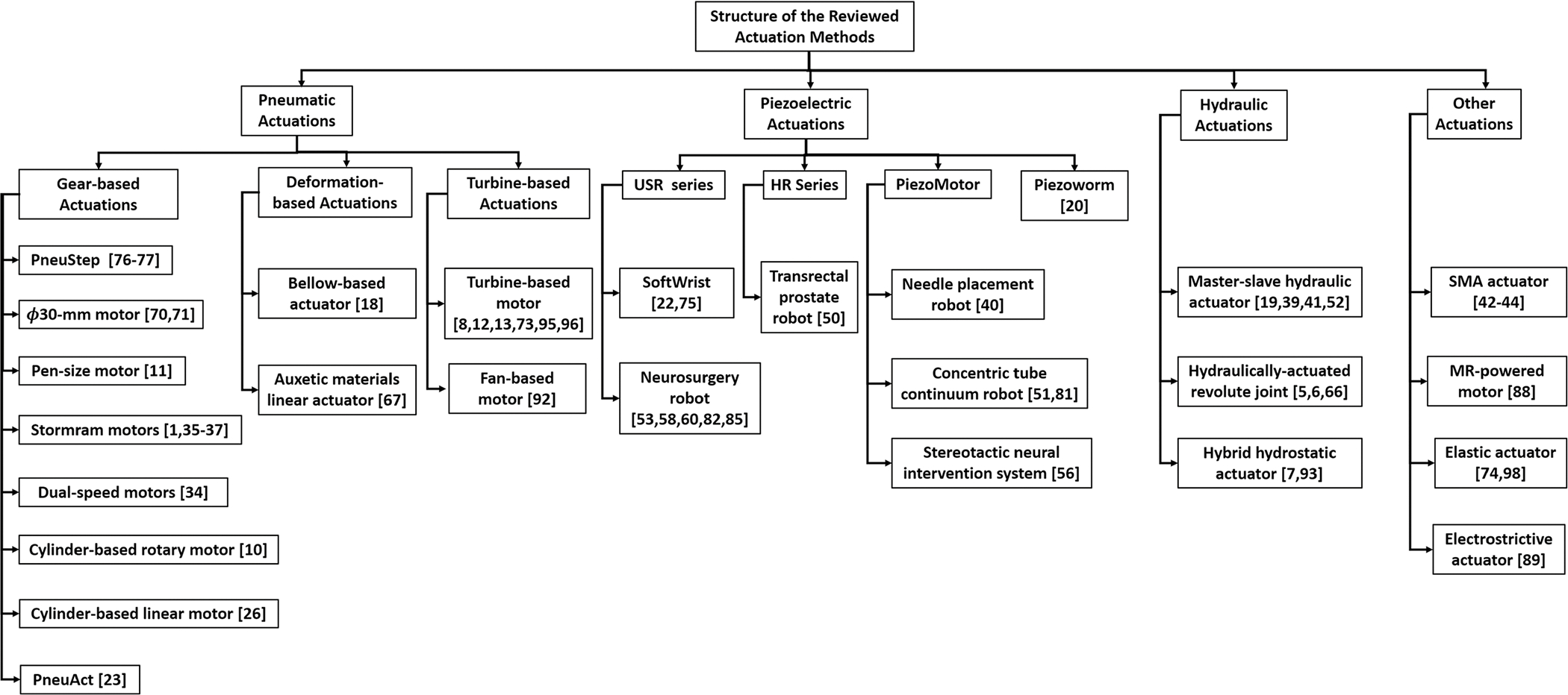
Magnetic resonance imaging (MRI) is one of the most prevailing technologies to enable noninvasive and radiation-free soft tissue imaging. Operating a robotic device under MRI guidance is an active research area that has the potential to provide efficient and precise surgical therapies. MR-conditional actuators that can safely drive these robotic devices without causing safety hazards or adversely affecting the image quality are crucial for the development of MR-guided robotic devices. This paper aims to summarize recent advances in actuation methods for MR-guided robots and each MR-conditional actuator was reviewed based on its working principles, construction materials, the noteworthy features, and corresponding robotic application systems, if any. Primary characteristics, such as torque, force, accuracy, and signal-to-noise ratio (SNR) variation due to the variance of the actuator, are also covered. This paper concludes with a perspective on the current development and future of MR-conditional actuators.

Keywords: Actuation; Hydraulic; MR-conditional; Magnetic resonance imaging (MRI); Motor; Piezoelectric; Pneumatic.


Conflict of interest statement

CONFLICT OF INTEREST

None to declare.

Figures

FIGURE 1.
FIGURE 1.
MR-conditional actuation methods.
FIGURE 2.
FIGURE 2.
(a) PenuStep motor principle, (b) kinematics diagram of PneuStep motor.
FIGURE 3.
FIGURE 3.
(a) φ30-mm motor parts and (b) assembly drawing of the φ30-mm motor.
FIGURE 4.
FIGURE 4.
CAD drawing of pen-size stepper motor.
FIGURE 5.
FIGURE 5.
(a) Principle of Stormram linear stepper motor and (b) principle of Stormram curved stepper motor.
FIGURE 6.
FIGURE 6.
(a) rotational dual-speed pneumatic motor and (b) the prototype of the linear and rotational dual-speed pneumatic motor.
FIGURE 7.
FIGURE 7.
(a) Component of cylinder-based rotary motor and (b) working procedures of the cylinder-based rotary motor.
FIGURE 8.
FIGURE 8.
(a) Cylinder-based linear motor mechanism and (b) prototype of the needle placement robot.
FIGURE 9.
FIGURE 9.
(a) Assembly drawing of the PneuAct and (b) longitudinal cross section drawing of the PneuAct.
FIGURE 10.
FIGURE 10.
(a) assembly diagram of bellow-based actuation system and (b) the prototype of the bellow-based actuation system.
FIGURE 11.
FIGURE 11.
(a) prototype of Auxetic materials needle driver, (b) working phases of needle insertion, (c) envelope structure pattern unit, and (d) view of the outer envelope.
FIGURE 12.
FIGURE 12.
(a) Exploded view of the turbine-based motor and (b) prototype of turbine-based motor.
FIGURE 13.
FIGURE 13.
(a) assembly drawing fan-based motor and (b) the prototype of the fan-based motor.
FIGURE 14.
FIGURE 14.
(a) Configuration of MR-SoftWrist, (b) phantom test in scanner room, and (c) robot end effector DOFs.
FIGURE 15.
FIGURE 15.
(a) APT-III actuated robot with rotation stage and (b) APT-III actuated robot with translation stage.
FIGURE 16.
FIGURE 16.
(a) Needle placement robot configuration and (b) phantom test installation.
FIGURE 17.
FIGURE 17.
Piezoworm actuation model.
FIGURE 18.
FIGURE 18.
Principle of the master–slave hydraulic actuator.
FIGURE 19.
FIGURE 19.
Cross-sectional view (a) and working principle and (b) of the HSC joint with embedded rack-and-pinion system. Assembly of hydraulically-actuated revolute joint (c).
FIGURE 20.
FIGURE 20.
(a) Working principle of rolling diaphragm cylinder: A is the principle of the cylinder, B is IER Fujikura DM3–20-20 diaphragm and molded-in O-ring at the base, (b) hydrostatic transmission: one air line (red) and one water line (blue) are connected to the actuators for 1-DOF robot, (c) prototype of the hybrid hydrostatic actuator.
FIGURE 21.
FIGURE 21.
(a) MINIR prototype, (b) MINIR revised prototype and (c) MINIR-II prototype.
FIGURE 22.
FIGURE 22.
(a) Assembly of MR-powered actuation and (b) phantom test of the robot system.
FIGURE 23.
FIGURE 23.
(a) Exploded view of MR-conditional SEA and (b) the robotic system prototype.,
FIGURE 24.
FIGURE 24.
(a) The single actuator integrated cod design and (b) the multi-actuator modular coil design.

References

    1. Abdelaziz ME, Groenhuis V, Veltman J, Siepel F, and Stramigioli S. Controlling the Stormram 2: an MRI-compatible robotic system for breast biopsy. In 2017 IEEE International Conference on Robotics and Automation (ICRA). IEEE, pp. 1746–1753, 2017.
    1. Alvara AN, Looi T, Saab R, Shorter A, Goldenberg A, and Drake J. Development and validation of MRI compatible pediatric surgical robot with modular tooling for bone biopsy. In 2018 IEEE/RSJ International Conference on Intelligent Robots and Systems (IROS). IEEE, pp. 4935–4941, 2018.
    1. ASTM International. ASTM F2503–13 Standard Practice for Marking Medical Devices and Other Items for Safety in the Magnetic Resonance Environment. West Conshohocken, PA: ASTM, 2013.
    1. Bosboom DGH, Fütterer JJ, and Bosboom J. Bosboom DGH, Fütterer JJ, and Bosboom J, “Motor system, motor, and robot arm device comprising the same. Google Patents, 2016.
    1. Bruyas A, Geiskopf F, Meylheuc L, and Renaud P. Combining multi-material rapid prototyping and pseudorigid body modeling for a new compliant mechanism. In 2014 IEEE International Conference on Robotics and Automation (ICRA). IEEE, pp. 3390–3396, 2014.

MeSH terms