Review
. 2020 Aug 27;10(9):645.
doi: 10.3390/diagnostics10090645.

Artifacts in Musculoskeletal Ultrasonography: From Physics to Clinics

Affiliations
Review

Artifacts in Musculoskeletal Ultrasonography: From Physics to Clinics

Wei-Ting Wu et al. Diagnostics (Basel). .

Abstract

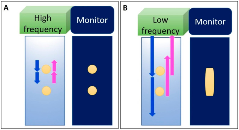
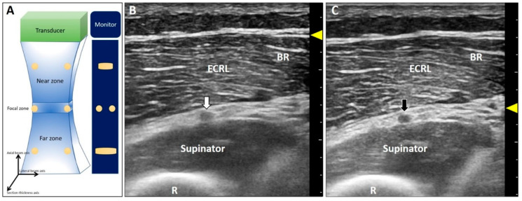
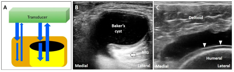
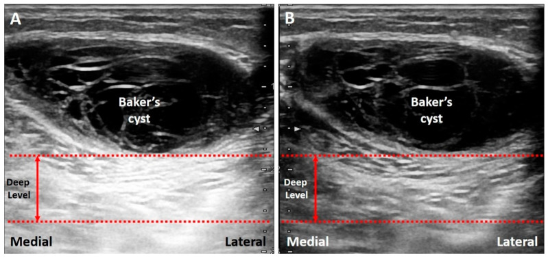
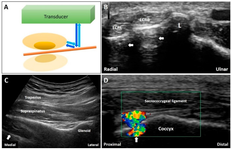
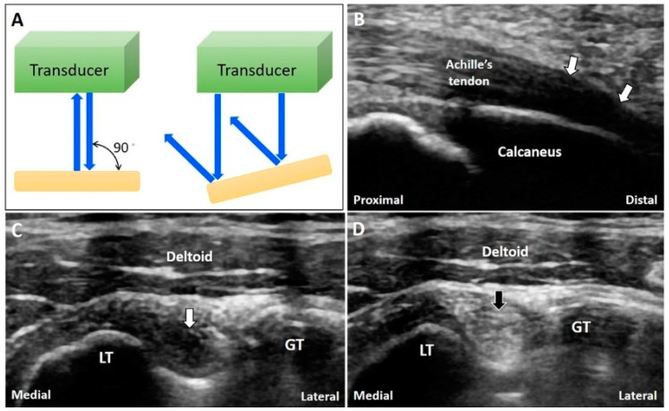
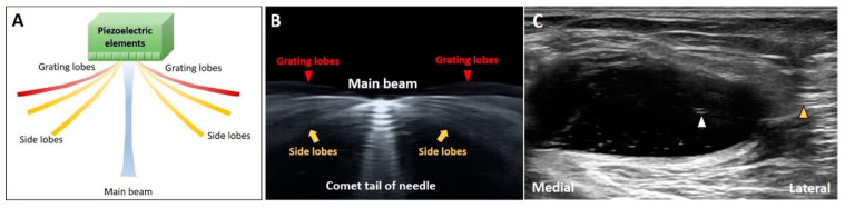
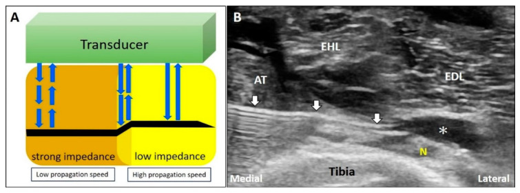
Ultrasound appears to be the most useful imaging tool in the diagnosis and guided treatment of musculoskeletal disorders. However, ultrasonography has been criticized for being user dependent. Therefore, medical professionals should be familiar with the basic principles of ultrasound imaging (e.g., physics and technical skills) to diminish artifacts and avoid misinterpretation. In this review, we focused on the physics of common artifacts, their clinical significance, and the ways to tackle them in daily practice during musculoskeletal imaging. In particular, artifacts pertaining to the focal zone, beam attenuation, path and side lobe of the beam, speed of the sound, and range ambiguity were described.

Keywords: artifact; attenuation; beam; musculoskeletal; reflection; ultrasound.


Conflict of interest statement

The authors declare no conflict of interest.

Figures

Figure 1
Figure 1
Axial resolution of the US image is related to the frequency. Two objects can be clearly differentiated when their distance is greater than half of the spatial pulse length (A). If the distance is smaller than half of the pulse length, the two objects cannot be differentiated during US imaging (B). Blue arrow: the projected US signals; pink arrow: the returned US signals. Yellow circles: the objects in the tissue or the US images of the objects insonated by high frequency US signals.Yellow column: the overlapped images derived from the two vertically aligned objects. Yellow circles: the objects in the tissue or the US images of the objects insonated by high frequency US signals. Yellow column: the overlapped images derived from the two vertically aligned objects.
Figure 2
Figure 2
The US beam width is the narrowest at the focal zone with the best lateral resolution of two objects perpendicular to the beam (A). The deep radial nerve is blurred at the far zone (B) and becomes clearer when the focus has been set at the same depth as the nerve (C). White arrow: the blurred image of the deep radial nerve due to the improper location of the focal zone; black arrow: the clear image of the deep radial nerve after adjustment of the focal zone; yellow arrowheads: focal zone. ECRL: extensor carpi radialis longus muscle; BR: brachioradialis muscle; R: radius.
Figure 3
Figure 3
If the US beam passes through a low-attenuating structure, the signals reflected from the deep structure increase in relation to the surrounding tissues (A). The areas deep to a Baker’s cyst (B) and a complete tear of the supraspinatus tendon (C) become hyperechoic because of the posterior acoustic enhancement (and discrepancy of the acoustic impedance between two different tissues). White arrow: artifact due to posterior acoustic enhancement; white arrowhead: cartilage interface sign. MG: medial gastrocnemius muscle. Blue arrows: the projected and reflected US beams. Black circle: the low-attenuation structure.
Figure 4
Figure 4
The area deep to the Baker’s cyst is hyperechoic, making it difficult to differentiate the echotexture (A). Decreasing the signal gain at the deep level can reduce the posterior enhancement and help in clarification of the echotexture (B). Red dash line: the level deep to the target. Red double arrow: the range of the depth regarding the area highly influenced by the artifact.
Figure 5
Figure 5
When the US wave passes through a high-attenuating structure, the echo behind the structure would be significantly reduced; forming a clean, partial, or dirty acoustic shadowing. Blue arrows: the projected and reflected US beams. Dark yellow circles: high-attenuation objects. Light yellow circles: gas bubbles.
Figure 6
Figure 6
Below the large or egg-shelled calcifications, clean acoustic shadowing can be observed (A). Partial acoustic shadowing is observed deep to fragmented calcifications resulting from the heterotrophic ossification in rectus femoris muscle (B). Dirty acoustic shadowing can be observed behind the gas bubbles during an US-guided injection (C). Yellow arrow: acoustic shadowing artifact; white arrowhead: gas bubbles; yellow arrowhead: dirty acoustic shadowing; green arrow: needle. SS: supraspinatus tendon; EDC: extensor digitorum communis muscle.
Figure 7
Figure 7
Schematic drawing illustrates multiple reverberations occurring between the two closely reflective interfaces (A). The comet tail appearance can be observed deep to the needle (B). White arrow: needle; yellow arrowhead: reverberation artifact. SS: supraspinatus tendon. Blue and black Arrows: the projected and reflected US beams.
Figure 8
Figure 8
The schematic drawing illustrates the ring-down artifacts when the US waves pass through the air bubbles (A). During imaging for inguinal hernia, the ring-down artifacts can be seen in the bowels (B). During intercostal block, the ring-down artifacts can be visualized deep to the pleura (C). White arrow: ring-down artifacts. RA: rectus abdominis. Black and blue arrow: the projected and reflected US beams.
Figure 9
Figure 9
When the sound waves encounter a reflective interface, the reflected beam would cast a mirror image at the opposite side of the interface (A). The mirror artifacts can be seen at many body regions like the forearm (B), supraspinatus fossa (C), and coccyx (D). White arrow: mirror artifact. ECRL: extensor carpi radialis longus tendon; ECRB: extensor carpi radialis brevis tendon; L: Lister’s tubercle Blue arrows: the projected and reflected US beams. Brown pillar: the reflective interface. Green box: the color box for detection of Doppler signals.
Figure 10
Figure 10
The US beam is totally reflected back when the transducer is perpendicular to the target while they are reflected away from the transducer if the object is not perpendicular to the US beam (A). The anisotropy is seen at the insertion of the Achilles tendon (B). A normal biceps long head tendon can be misinterpreted as tendinopathy due to anisotrophy (C) and tilting the transducer to make it perpendicular to the bicipital groove can eliminate the artifact (D). White arrow: anisotropy artifact; black arrow: image after compensation. GT: greater tubercle; LT: lesser tubercle. Blue arrows: the projected and reflected US beams.
Figure 11
Figure 11
Schematic drawing illustrates the directions of the central beam and lateral dispersion of residual off-axis beams (side and grating lobes) (A). The lateral dispersion of US beams can be clearly observed with a lot of coupling agents in between the needle and transducer (B). The side lobe artifact can be observed inside the cystic lesion (C). Yellow arrow: side lobe; red arrowheads: grating lobes; white arrowhead: nail plate. White arrowhead: the ghost image on the main axis of the US beam. Yellow arrowhead: the object on the path of the side lobe that causes the side lobe artifact.
Figure 12
Figure 12
When the US beam travels through an area with strong impedance, the delayed return of the US signals to the transducer would lead to overestimation of the depth of the object. In contrast, if the target is located in the area of low acoustic impedance, the object shown on the monitor would appear shallower that its actual depth (A). During deep peroneal (fibular) nerve block; as the propagation speed of sound waves in the muscle is faster than that in the fat, the needle shaft in the fat pad will be seen bended toward the tibia bone (B). White arrow: refraction artifact; asterisks: injectate. AT: tibialis anterior muscle; EHL: extensor hallucis longus muscle; EDL: extensor digitorum longus muscle; N: deep peroneal (fibular) nerve. Blue arrows: the projected and reflected US beams.
Figure 13
Figure 13
Schematic drawing illustrates the hypoechoic parallel lines projecting along the edges of the curved structure because most of the US beam is reflected away from the transducer (A). The edge artifact can be observed at the edges of a circular structure, such as a schwannoma of the lateral sural cutaneous nerve (B). This artifact may be misinterpreted as thickened Achilles paratenon (C). White arrow: edge artifact; yellow arrowhead: sutures; yellow asterisk: acoustic shadowing due to sutures. GC: gastrocnemius muscle.
Figure 14
Figure 14
Schematic drawing illustrates that the first US pulse (dark blue arrow) hits the object and returns to the transducer after the second pulse (bright blue arrow) is projected. The US machine misrecognizes the first returning pulse as the second returning pulse (bright blue arrow with dark blue frame). A ‘ghost’ object will appear at a more superficial level because its depth is underestimated (A). US imaging of a huge Baker’s cyst is accompanied by the artifact as intracystic septae because of the echoes from the deep wall of the cyst (B). Yellow arrow: range ambiguity artifact.

Similar articles

Cited by

References

    1. Chang K.-V., Wu W.-T., Hsu P.-C., Lew H.L., Özçakar L. Clinical Tests of the Shoulder. Am. J. Phys. Med. Rehabil. 2020;99:161–169. doi: 10.1097/PHM.0000000000001311. - DOI - PubMed
    1. Bianchi S., Hoffman D.F., Tamborrini G., Poletti P. Ultrasound Findings in Less Frequent Causes of Carpal Tunnel Syndrome. J. Ultrasound Med. 2020 doi: 10.1002/jum.15349. - DOI - PubMed
    1. Bianchi S., Beaulieu J.-Y., Poletti P.-A. Ultrasound of the ulnar-palmar region of the wrist: Normal anatomy and anatomic variations. J. Ultrasound. 2020:1–14. doi: 10.1007/s40477-020-00468-5. - DOI - PMC - PubMed
    1. Ciloglu O., Karaali E., Gorgulu F.F., Ekiz T. Ultrasonographic evaluation of the patellar tendon length and elasticity after open-wedge high tibial osteotomy: A comparison with radiological and clinical parameters. Knee. 2020;27:1128–1134. doi: 10.1016/j.knee.2020.05.016. - DOI - PubMed
    1. Wu W.-T., Chang K.-V., Mezian K., Naňka O., Lin C.-P., Özçakar L. Basis of Shoulder Nerve Entrapment Syndrome: An Ultrasonographic Study Exploring Factors Influencing Cross-Sectional Area of the Suprascapular Nerve. Front. Neurol. 2018;9:902. doi: 10.3389/fneur.2018.00902. - DOI - PMC - PubMed

LinkOut - more resources