Review
. 2020 Oct 14;120(19):10887-10949.
doi: 10.1021/acs.chemrev.0c00027. Epub 2020 Sep 1.

Biomaterials for Bioprinting Microvasculature

Affiliations
Review

Biomaterials for Bioprinting Microvasculature

Ryan W Barrs et al. Chem Rev. .

Abstract

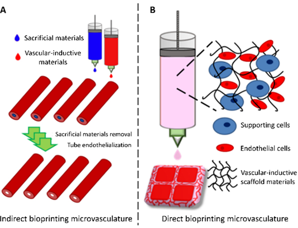
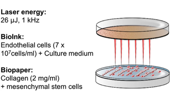
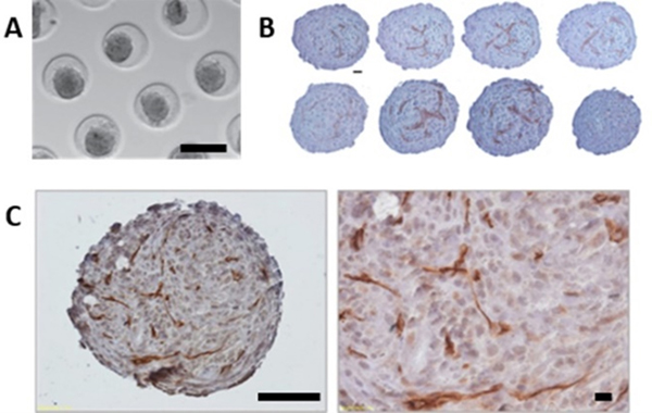
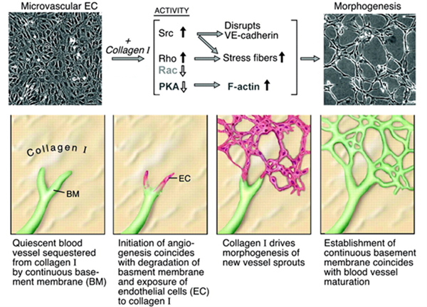
Microvasculature functions at the tissue and cell level, regulating local mass exchange of oxygen and nutrient-rich blood. While there has been considerable success in the biofabrication of large- and small-vessel replacements, functional microvasculature has been particularly challenging to engineer due to its size and complexity. Recently, three-dimensional bioprinting has expanded the possibilities of fabricating sophisticated microvascular systems by enabling precise spatiotemporal placement of cells and biomaterials based on computer-aided design. However, there are still significant challenges facing the development of printable biomaterials that promote robust formation and controlled 3D organization of microvascular networks. This review provides a thorough examination and critical evaluation of contemporary biomaterials and their specific roles in bioprinting microvasculature. We first provide an overview of bioprinting methods and techniques that enable the fabrication of microvessels. We then offer an in-depth critical analysis on the use of hydrogel bioinks for printing microvascularized constructs within the framework of current bioprinting modalities. We end with a review of recent applications of bioprinted microvasculature for disease modeling, drug testing, and tissue engineering, and conclude with an outlook on the challenges facing the evolution of biomaterials design for bioprinting microvasculature with physiological complexity.


Figures

Figure 1.
Figure 1.
Bioprinting microvasculature. Indirect and direct approaches employ biomaterials in different manners to fabricate microvessels.
Figure 2.
Figure 2.
Models of vessel formation. The several known models of blood vessel formation under physiological and pathological conditions. (A-C) Vessel generation under normal conditions: (A) sprouting angiogenesis; (B) vasculogenesis – endothelial progenitors differentiate into ECs and supporting cells to forming vessels; (C) intussusception – vessel splitting into two new vessels. (D-F) Vessel generation in the tumoral environment: (D) vessel co-option induced by tumor cells; (E) vascular mimicry – tumor vessels can be lined by tumor cells along with normal ECs; (F) tumor cell to EC differentiation – tumor vessels can also be lined by the tumoral differentiated ECs. Reproduced with permission from ref. . Copyright 2016 Springer Nature.
Figure 3.
Figure 3.
The roles of growth factors in neovascularization. Spatiotemporal regulation from various growth factors, cytokines, and enzymes orchestrates vasculogenesis, to form primitive capillary network. Angiogenesis occurs with an existing capillary network, and forms neovessels through sequential processes regulated by growth factors, cytokines, and guidance molecules. Extracellular matrix degradation, endothelial cell migration, stalk elongation, and vascular stabilization are regulated by different proteinases and their corresponding inhibitors. Adapted with permission from ref. . Copyright 2017 Elsevier.
Figure 4.
Figure 4.
ECM microenvironment during angiogenesis. (A) Angiogenesis can be triggered by vessel narrowing induced hypoxia. The hypoxic cells secrete proteases to degrade ECM, altering the physical and chemical properties of ECM. The cells also secrete growth factors, which are sequestered by proteoglycans to create a chemokine gradient. Meanwhile, surrounding capillaries sense these changes and initiate multiple responses, such as vessel sprouting. (B) Sprouting endothelial cells simultaneously adhere to surrounding ECM via integrins while sensing sequestered growth factors through cell surface receptor tyrosine kinases. Concerted growth factor and integrin activation drive synergistic angiogenic signaling towards restoring blood flow to hypoxic cells. Reproduced with permission from ref. . Copyright 2016 Springer Nature.
Figure 5.
Figure 5.
Thermal inkjet bioprinting triggers the activation of the VEGF pathway. The schematic illustration shows how heat from the printing process causes cellular heat stress leading to various pathways in which extracellular heat-shock proteins play an angiogenic role. Reproduced with permission from ref. . Copyright 2019 IOP Publishing Ltd.
Figure 6.
Figure 6.
Coaxial extrusion-based bioprinting. Solid or hollow hydrogel fibers can be printed with a coaxial nozzle depending on which axis (core or shell) the hydrogel and crosslinker are extruded through. Reproduced with permission from ref. . Copyright 2015 John Wiley and Sons.
Figure 7.
Figure 7.
Embedded 3D bioprinting of vascular structures. (A) Approach for directly bioprinting vascular structures within a supportive bath based on crosslinking of the bioink and removal of the supportive bath after printing. Adapted from ref. . Copyright 2019 Elsevier Ltd. under the terms of the Creative Commons (CC BY 4.0) License https://creativecommons.org/licenses/by/4.0/. (B) Example of perfusable vasculature printed in a sacrificial gelatin support bath using an alginate bioink. Reproduced from ref. . Copyright 2015 American Association for the Advancement of Science under the terms of the Creative Commons (CC BY 4.0) License https://creativecommons.org/licenses/by/4.0/. (C) Approach for indirectly bioprinting vascular structures within a supportive bath based on crosslinking of the bath materials (i.e. by UV exposure) and removal of the sacrificial bioink after printing. Adapted from ref. . Copyright 2019 Elsevier Ltd. under the terms of the Creative Commons (CC BY 4.0) License https://creativecommons.org/licenses/by/4.0/. (D) Example of perfusable microvascular networks embedded within a photopolymerized Pluronic F127‐diacrylate matrix using a sacrificial Pluronic F127 bioink. Reproduced from ref. . Copyright 2011 WILEY‐VCH Verlag GmbH & Co. KGaA, Weinheim.
Figure 8.
Figure 8.
LIFT bioprinting of endothelial cells. Schematic illustration shows optimal parameters for LIFT bioprinting of endothelial cells. Reproduced with permission from ref. . Copyright 2019 Springer Nature.
Figure 9.
Figure 9.
Direct writing of microvasculature using laser-assisted direct writing. Schematic illustration of microvascular patterning within a cell-laden hydrogel using a focalized pulsed laser and an example of patterned microvasculature using this technique. Scale bar = 100 μm. Adapted with permission from ref. . Copyright 2016 John Wiley and Sons.
Figure 10.
Figure 10.
Projection-based stereolithography for patterning microvasculature. Perfusable capillary-scale networks can be patterned into photoreactive hydrogels via user-defined photomasks. Reproduced with permission from ref. . Copyright 2018 American Chemical Society.
Figure 11.
Figure 11.
Multiscale vascularized constructs printed with tissue strands. Hollow vascular networks can be printed in tandem with tissue-specific aggregate strands to provide mechanical support and media perfusion. Endothelial cells within tissue strands self-organize and create capillary networks that functionally anastomose with adjacent vascular networks under perfusion. Reproduced with permission from ref. . Copyright 2014 American Society of Mechanical Engineers.
Figure 12.
Figure 12.
Prevascularized spheroids for scaffold-free bioprinting. (A) Fabrication of spheroids by gravity-induced aggregation in agarose microwells (scale bar = 200 μm). (B) Sequential sections of two large HUVEC/HFF/ADSC fused spheroids (scale bar = 20 μm). (C) Capillary-like network formation in fused constructs composed of HUVEC/HFF/ADSC spheroids. Overview scale bar = 100 μm (left), 40x objective magnification scale bar = 20 μm (right). Adapted with permission from ref. . Copyright 2018 IOP Publishing Ltd.
Figure 13.
Figure 13.
Ideal bioinks for bioprinting microvasculature. Created with BioRender.com.
Figure 14.
Figure 14.
Influence of collagen I signaling on capillary morphogenesis in vitro. Collagen type I activates Src and Rho and suppresses Rac and PKA through β1 integrins. This results in induction of actin stress fibers, disruption of VE-cadherin, and formation of precapillary cords. Degradation of basement membrane and exposure of activated and proliferating ECs to collagen type I initiates morphogenesis of new capillary sprouts. Adapted with permission from ref. . Copyright 2005 Wolters Kluwer Health, Inc.
Figure 15.
Figure 15.
Rheological properties of collagen bioinks before, during, and after gelation at 37 °C. (A) Storage modulus (G’) of bioink at 4 °C before gelation. (B) G’ of bioink after complete gelation at 37 °C. (C) Maximum growth rate of G’ after increasing temperature to 37 °C. (D) Crossover time of G’ and G’’ after increasing temperature to 37 °C. * indicates significant difference (p < 0.05) compared to pH 7.0–7.5. Reproduced with permission from ref. . Copyright 2017 IOP Publishing Ltd.
Figure 16.
Figure 16.
In situ patterning of microvasculature in collagen hydrogels with laser-assisted direct writing. (A) Schematic representation of the gel size range and microfluidic network geometry that can be processed. (B) Confocal 3D reconstruction of a hollow endothelial cell tube (HUVECs) formed in collagen type I. Adapted with permission from ref. . Copyright 2016 John Wiley and Sons.
Figure 17.
Figure 17.
Angiogenic sprouting in fibrin gels. (A) Angiogenic sprouting from a HUVEC-coated bead embedded in fibrin in the presence of skin fibroblasts. (B) Scanning electron micrograph of polymerized fibrin network. (A) Reproduced with permission from ref. . Copyright 2003 Elsevier Ltd. (B) Reproduced with permission from ref. . Copyright 2009 The Royal Society.
Figure 18.
Figure 18.
Printed human microvasculature in fibrin scaffold. (A) Printed fibrin scaffold using modified HP Deskjet 500 thermal inkjet printer. (B) Shape of printed fibrin scaffold after printing. (C) Individual printed fiber. (D) Printed microvasculature after 21 days. Reproduced with permission from ref. . Copyright 2009 Elsevier Ltd.
Figure 19.
Figure 19.
Functional multi-scale vasculature generated by combining direct and indirect bioprinting. (A) Schematics of the growth and maturation process of bioprinted multi-scale vascular system. Perfusable endothelialized vessels are patterned within collagen using sacrificial gelatin bioink. Perfusion of the channels promotes angiogenic sprouting and capillary network formation within the adjacent cell-laden fibrin gel. (B) Diffusion of 10 kDa Dextran is enhanced with capillary networks compared to without. Adapted with permission from ref. . Copyright 2014 Springer Nature.
Figure 20.
Figure 20.
Synthesis and characterization of methacrylated gelatin. (A) Gelatin macromers containing primary amine groups are reacted with methacrylic anhydride (MA) to add methacrylate pendant groups. (B) Methacrylated gelatin is crosslinked using UV irradiation in the presence of a photoinitiator to yield a covalently crosslinked hydrogel. (C) Compressive modulus for 5%, 10% and 15% (w/v) GelMA at low (~20%), medium (~50%), and high (~80%) degrees of methacrylation. Adapted with permission from ref. . Copyright 2010 Elsevier Ltd.
Figure 21.
Figure 21.
Bioprinting microvessels with GelMA/alginate bioinks. Several coaxial systems have been developed to bioprint (A) hollow, (B) solid, (C) morphology-controllable, and (D) multi-layer hollow GelMA/alginate microfibers. (A) Adapted from ref. . Copyright 2016 John Wiley and Sons. (B) Adapted with permission from ref. . Copyright 2016 Elsevier Ltd. (C) Adapted from ref. . Copyright 2018 John Wiley and Sons. (D) Adapted with permission from ref. . Copyright 2018 John Wiley and Sons.
Figure 22.
Figure 22.
VEGF-conjugated GelMA bioink. (A) Schematic for the preparation of –COOH modified GelMA and chemical conjugation of VEGF. (B) Endothelial cell sprouting inside VEGF‐conjugated and nonconjugated bioprinted GelMA hydrogels. Adapted with permission from ref. . Copyright 2017 John Wiley and Sons.
Figure 23.
Figure 23.
VEGF-peptide functionalized GelMA enhances microvascularization. (A) Synthesis of GelMA covalently immobilized with acrylated QK VEGF-mimetic peptide. (B) GelMA+AcQK hydrogels enhanced formation of tubular networks compared to unmodified GelMA. Scale bars = 100 μm. Adapted with permission from ref. . Copyright 2017 Elsevier Ltd.
Figure 24.
Figure 24.
Rheological behavior of tissue-specific dECM bioinks. (A) Sol-gel transition of dECM pre-gels prepared from cartilage dECM (cdECM), heart dECM (hdECM) and adipose dECM (adECM). (B-D) Rheological properties of the dECM pre-gels; (B) viscosity at 15 °C, (C) gelation kinetics from 4 °C to 37 °C, and (D) dynamic modulus at varying frequency at 37 °C. Reproduced with permission from ref. . Copyright 2014 Springer Nature.
Figure 25.
Figure 25.
Coaxial bioprinting functional microvasculature with vascular-derived dECM bioinks. (A) Coaxial cell‐printed vessels using HUVECs‐laden VdECM/alginate hybrid bioink. (B, C) Angiogenic capillary sprouting of microvessels into collagen hydrogel containing proangiogenic growth factors [scale bars: 200 μm (B) and 50 μm (C)]. Adapted with permission from ref. . Copyright 2018 John Wiley and Sons.
Figure 26.
Figure 26.
Personalized dECM bioinks for autologous bioprinting of microvascularized constructs. (A and B) Human omentum tissue (A) before and (B) after decellularization. (C) dECM hydrogel at room temperature (left) and after gelation at 37 °C (right). (D) Rheological characterization of 1% w/v and 2.5% w/v omentum hydrogels, exhibiting gelation at 37 °C. (E) A 3D model of a vascularized cardiac patch. (F) Concept of printing vascularized, patient-specific cardiac tissue with distinct cellular bioinks. (G) A patient-specific cardiac patch printed with blood vessels (CD31 in green) embedded within cardiac tissue (actinin in pink). (H) Cross‐section of a single lumen, showing the interaction of GFP‐expressing ECs and RFP‐expressing fibroblasts. Adapted from ref. . Copyright 2019 WILEY‐VCH Verlag GmbH & Co. KGaA, Weinheim under the terms of the Creative Commons (CC BY 4.0) License https://creativecommons.org/licenses/by/4.0.
Figure 27.
Figure 27.
Bioprinted agarose microchannels. Agarose hydrogel fibers (green) with diameters ranging from 250–500 μm could be printed and cast in a GelMA hydrogel before being removed and perfused with fluorescent beads (pink) or endothelial cells. Reproduced with permission from ref. . Copyright 2015 Royal Society of Chemistry.
Figure 28.
Figure 28.
Printable alginate bioink formulations for droplet-based bioprinting. Summary table of the preferable range of alginate bioink formulations with high printability (green) based on three important printability criteria: homogeneous cell suspension, high printing resolution, and high cell viability. Reproduced with permission from ref. . Copyright 2014 Elsevier Ltd.
Figure 29.
Figure 29.
Patterning vascular networks in a pre-polymer support matrix with sacrificial alginate bioink. (A) Schematic of fabricating patterned vascular networks by direct writing alginate bioink inside the pre-polymer of hydrogels. (B) Patterned templates and (C) hollow microchannels printed with sacrificial alginate within a GelMA support matrix. (D) Cross-sections of microchannels with varying diameters fabricated with the direct writing approach. Reproduced with permission from ref. . Copyright 2019 Springer Nature.
Figure 30.
Figure 30.
Alginate-based bioink with autologous growth factors. Platelet-rich plasma (PRP) is incorporated within alginate to form the bioink and can be bioprinted to form a scaffold embedded with autologous growth factors. Adapted with permission from ref. . Copyright 2018 John Wiley and Sons.
Figure 31.
Figure 31.
Bioprinting microvasculature with carbohydrate glass. Hydrogels can be cast around sacrificial glass networks and implanted to functionally anastomose with host microvasculature, forming chimeric vessels. Adapted with permission from ref. . Copyright 2017 Springer Nature.
Figure 32.
Figure 32.
Engineered vascular network from pluripotent stem cells within a hyaluronic acid hydrogel matrix. (A) Human pluripotent stem cells (PSCs) differentiate into early vascular cells that can mature into functional endothelial cells (i) and perivascular cells (ii) when placed within a designer synthetic hyaluronic acid (HA) hydrogel. (B) PSC-derived EVCs self-assemble into networks in HA hydrogels (i) and form hollow capillary structures stabilized by NG2+ perivascular cells (ii). Reproduced with permission from ref. . Copyright 2014 Company of Biologists.
Figure 33.
Figure 33.
Supramolecular guest-host hyaluronic acid bioinks. Physically crosslinked guest-host HA hydrogels can serve as sacrificial bioinks while methacrylated guest-host HA hydrogels can be covalently crosslinked by UV to form a mechanically stabilized bioink. Sacrificial guest-host HA bioinks can be embedded within stabilized guest-host MeHA hydrogels to fabricate a perfusable network (scale bar = 500 μm). Adapted with permission from ref. . Copyright 2017 Spring Nature.
Figure 34.
Figure 34.
Schematic of proteolytically-degradable PEG hydrogels to promote vascular morphogenesis. The ↓ represents an MMP-cleavable site. Adapted from ref. with permission. Copyright 2010 Elsevier Ltd.
Figure 35.
Figure 35.
The PEGX method for tuning bioink printability. (A) Polymer or polymer mixtures can be linear (e.g., gelatin), branched (e.g., 4 arm PEG amine), or multifunctional (e.g., gelatin methacrylate). (B) PEGX can be linear or multiarm and can be various chain lengths. (C) Cells can be optionally incorporated by (D) mixing with polymers and PEGX to form the bioink. (E) Secondary crosslinking can increase mechanical robustness after printing. (F) By changing the reactive groups of PEGX, polymers of other functional groups may be crosslinked. (G) Printing process of PEGX bioink method and corresponding phase. Reproduced with permission from ref. . Copyright 2015 John Wiley and Sons.
Figure 36.
Figure 36.
Direct writing microvasculature in functionalized PEG hydrogels. (A) Multiphoton excitation induces localized degradation via oNB photocleavage, resulting in microchannel (pink) generation in the presence of embedded stromal cells (green). (B) A fabricated 3D hierarchical vascular network comprised of one 300 μm × 300 μm channel branching into four 100 μm × 100 μm channels and then terminating in 16 channels, each with 25 μm × 25 μm cross‐section. (C) Cross‐sectional views of the branched microvascular network indicate patent vascular lumens. (D) Biomimetic capillary networks can be created with user‐defined geometrical control within the hydrogel. Endothelialization of (E,F) 60 μm × 60 μm and (G,H) 45 μm × 45 μm (width × height) channels was achieved. Adapted from ref. . Copyright 2017 John Wiley and Sons.
Figure 37.
Figure 37.
Microvascularized 3D tissue fabrication with Pluronic F127 fugitive bioinks. (i) Fugitive (vascular) ink, which contains pluronic and thrombin, and cell-laden inks, which contain gelatin, fibrinogen, and cells, are printed within a 3D perfusion chip. (ii) ECM material, which contains gelatin, fibrinogen, cells, thrombin, and TG, is then cast over the printed inks. After casting, thrombin induces fibrinogen cleavage and rapid polymerization into fibrin in both the cast matrix, and through diffusion, in the printed cell ink. Similarly, TG diffuses from the molten casting matrix and slowly cross-links the gelatin and fibrin. (iii) Upon cooling, the fugitive ink liquefies and is evacuated, leaving behind a pervasive vascular network, which is (iv) endothelialized and perfused via an external pump. Reproduced with permission from ref. .
Figure 38.
Figure 38.
Applications of bioprinting microvasculature for disease modeling and drug testing. (A) Cardiac applications include encapsulating HUVECs inside bioprinted microfibers to create confluent epithelial layers and seeding the scaffold with cardiomyocytes to create an endothelialized myocardial tissue. Adapted with permission from ref. . Copyright 2016 Elsevier Ltd. (B) Vascularized airway-on-a-chip models were fabricated from a 3D vascular network and an airway epithelium. Adapted with permission from ref. . Copyright 2018 IOP Publishing Ltd. (C) Liver modeling has included triculture bioprinted models of liver lobules. Adapted with permission from ref. . Copyright 2016 National Academy of Sciences. (D) Bioprinted kidney models have relied on interactions between proximal tubule epithelial cells (PTECs) and glomerular microvascular endothelial cells (GMECs) to examine renal reabsorption. Adapted with permission from ref. . Copyright 2016 National Academy of Sciences. (E) Intestinal model applications have included bioprinted structures that consist of an epithelial layer and a capillary region to simulate the villi of the intestine. Adapted with permission from ref. . Copyright 2018 American Chemical Society. (F) Applications of bioprinting microvasculature have been used in placental modeling to gain insights into preeclampsia and other reproductive diseases. Adapted with permission from ref. . Copyright 2019 John Wiley and Sons. (G) Various vascular parameters can be simulated with bioprinted microvascular models. Adapted with permission from ref. . Copyright 2018 John Wiley and Sons. (H) Bioprinted tumor models can be used to examine tumor metastasis. Adapted with permission from ref. . Copyright 2019 John Wiley and Sons.
Figure 39.
Figure 39.
Applications of bioprinting microvasculature for tissue engineering and regeneration. (A) Bone applications have included bioprinting of biphasic vascularized bone constructs. Adapted with permission from ref. . Copyright 2016 John Wiley and Sons. (B) In situ hand-held bioprinting has been used to engineer pre-vascularized dental pulp. Adapted with permission from ref. . Copyright 2019 Taylor & Francis. (C) Patient-specific coronary vasculature has been recapitulated with bioprinting of multiscale vascular structures. Adapted with permission from ref. . Copyright 2019 American Association for the Advancement of Science. (D) Muscle constructs have been fabricated through bioprinting for treatment and repair of volumetric muscle loss. Adapted with permission from ref. . Copyright 2019 Elsevier Ltd. (E) Applications for skin engineering and regeneration have consisted of in situ methods for wound repair. Adapted from ref. . Copyright 2019 Springer Nature under the terms of the Creative Commons (CC BY 4.0) License https://creativecommons.org/licenses/by/4.0/.

Similar articles

Cited by

References

    1. Sherwood L. Human Physiology: From Cells to Systems; Cengage learning, 2015.
    1. Fox SI Human Physiology 9th Editon; McGraw-Hill press, New York, USA, 2006.
    1. Murray CD The Physiological Principle of Minimum Work Applied to the Angle of Branching of Arteries. J Gen. Physiol 1926, 9, 835–841. - PMC - PubMed
    1. Sherman TF On Connecting Large Vessels to Small. The Meaning of Murray’s Law. J. Gen. Physiol 1981, 78, 431–453. - PMC - PubMed
    1. Barral J-P; Croibier A. In Visceral Vascular Manipulations; Barral J-P;Croibier A, Eds.; Churchill Livingstone: Oxford, 2011.

Publication types

Substances