. 2020 Aug 28;11(9):813.
doi: 10.3390/mi11090813.

Large-Scale Flow in Micro Electrokinetic Turbulent Mixer

Affiliations

Large-Scale Flow in Micro Electrokinetic Turbulent Mixer

Keyi Nan et al. Micromachines (Basel). .

Abstract

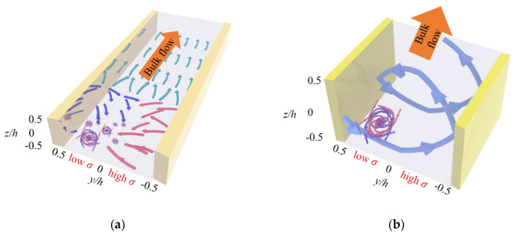
In the present work, we studied the three-dimensional (3D) mean flow field in a micro electrokinetic (μEK) turbulence based micromixer by micro particle imaging velocimetry (μPIV) with stereoscopic method. A large-scale solenoid-type 3D mean flow field has been observed. The extraordinarily fast mixing process of the μEK turbulent mixer can be primarily attributed to two steps. First, under the strong velocity fluctuations generated by μEK mechanism, the two fluids with different conductivity are highly mixed near the entrance, primarily at the low electric conductivity sides and bias to the bottom wall. Then, the well-mixed fluid in the local region convects to the rest regions of the micromixer by the large-scale solenoid-type 3D mean flow. The mechanism of the large-scale 3D mean flow could be attributed to the unbalanced electroosmotic flows (EOFs) due to the high and low electric conductivity on both the bottom and top surface.

Keywords: micro electrokinetic (μEK) turbulence; three-dimensional mean flow field; turbulent mixer; unbalanced electroosmotic flow.


Conflict of interest statement

The authors declare no conflict of interest.

Figures

Figure 1
Figure 1
Schematic diagram of experimental system and microchannel. (a) Schematic diagram of experimental system, include: ① 532 nm laser, ② beam expander, ③ reflect mirror, ④ dichroic mirror, ⑤ translation stage, ⑥ objective, ⑦ syringe pump, ⑧ camera; (b) Schematic diagram of the µEK turbulent mixer; (c) Coordinate system.
Figure 2
Figure 2
Profile of x-directional mean velocity U within the micromixer and at three different x positions without forcing. Dashed lines represent theoretical results. Symbols indicate experimental results from μPIV.
Figure 3
Figure 3
2D mean velocity fields at different z positions, with and without applying AC electric fields. The vector length has been normalized by the maximum velocity magnitude. (a,c,e) Unforced, and (b,d,f) forced. (a,b) z/h=0, (c,d) z/h = −0.25 and (e,f) z/h=0.5.
Figure 3
Figure 3
2D mean velocity fields at different z positions, with and without applying AC electric fields. The vector length has been normalized by the maximum velocity magnitude. (a,c,e) Unforced, and (b,d,f) forced. (a,b) z/h=0, (c,d) z/h = −0.25 and (e,f) z/h=0.5.
Figure 4
Figure 4
Velocity fluctuations under forcing evaluated by urms and vrms which are the root-mean-square values of u and v. (a,c,e) urms at different z positions. (b,d,f) vrms at different z positions. (a,b) z/h=0. (c,d) z/h=0.25. (e,f) z/h=0.5.
Figure 4
Figure 4
Velocity fluctuations under forcing evaluated by urms and vrms which are the root-mean-square values of u and v. (a,c,e) urms at different z positions. (b,d,f) vrms at different z positions. (a,b) z/h=0. (c,d) z/h=0.25. (e,f) z/h=0.5.
Figure 5
Figure 5
3D velocity vector on the yz planes at three different x positions (x/d = 0.06, 0.31, and 0.56). (a) Unforced, and (b) forced.
Figure 5
Figure 5
3D velocity vector on the yz planes at three different x positions (x/d = 0.06, 0.31, and 0.56). (a) Unforced, and (b) forced.
Figure 6
Figure 6
Schematic of the extraordinarily fast mixing process in the μEK turbulent mixer. (a) An extraordinarily fast mixing is achieved adjacent to the entrance, primarily on the low σ side and bias to negative z/h region, as indicated by the highly tangled arrows. (b) The well-mixed fluids that shown in (a) by the highly tangled arrows are convectively transported by the solenoid-type 3D mean flow (bold arrows) in the cross section and downstream. An overall uniform mixing can be rapidly realized.
Figure 7
Figure 7
x-directional vorticity on the yz planes of three different x positions. The velocity vector in the yz planes are also plotted. (a) x/d = 0.06, (b) x/d = 0.31, and (c) x/d = 0.56.

References

    1. Ma J., Wang Y., Liu J. Biomaterials Meet Microfluidics: From Synthesis Technologies to Biological Applications. Micromachines. 2017;8:255. doi: 10.3390/mi8080255. - DOI - PMC - PubMed
    1. Kang K.K., Lee B., Lee C.S. Microfluidic approaches for the design of functional materials. Microelectron. Eng. 2018;199:1–15. doi: 10.1016/j.mee.2018.07.007. - DOI
    1. Javanmard M., Talasaz A.H., Nemat-Gorgani M., Pease F., Ronaghi M., Davis R.W. Electrical detection of protein biomarkers using bioactivated microfluidic channels. Lab. Chip. 2009;9:1429–1434. doi: 10.1039/b818872f. - DOI - PMC - PubMed
    1. Sun B., Jiang J., Shi N., Xu W. Application of microfluidics technology in chemical engineering for enhanced safety. Process. Saf. Prog. 2016;35:365–373. doi: 10.1002/prs.11801. - DOI
    1. Wang F. Research Progress of Microfluidic Chips Preparation and its Optical Element. Sens. Transducers. 2014;166:29–38.

LinkOut - more resources