

Developments in Mannose-Based Treatments for Uropathogenic Escherichia coli-Induced Urinary Tract Infections
- PMID: 32876368
- PMCID: PMC7894189
- DOI: 10.1002/cbic.202000406
Developments in Mannose-Based Treatments for Uropathogenic Escherichia coli-Induced Urinary Tract Infections
Abstract
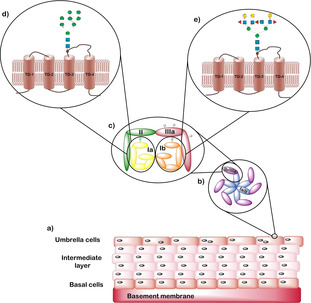
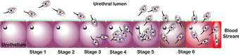
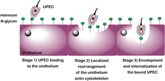
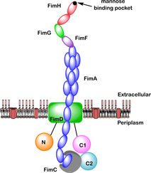
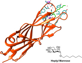
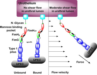
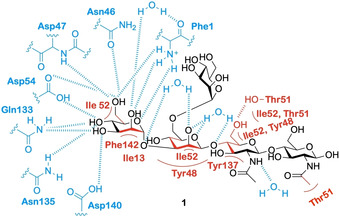
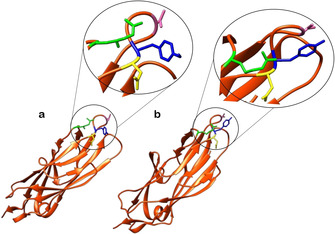
During their lifetime almost half of women will experience a symptomatic urinary tract infection (UTI) with a further half experiencing a relapse within six months. Currently UTIs are treated with antibiotics, but increasing antibiotic resistance rates highlight the need for new treatments. Uropathogenic Escherichia coli (UPEC) is responsible for the majority of symptomatic UTI cases and thus has become a key pathological target. Adhesion of type one pilus subunit FimH at the surface of UPEC strains to mannose-saturated oligosaccharides located on the urothelium is critical to pathogenesis. Since the identification of FimH as a therapeutic target in the late 1980s, a substantial body of research has been generated focusing on the development of FimH-targeting mannose-based anti-adhesion therapies. In this review we will discuss the design of different classes of these mannose-based compounds and their utility and potential as UPEC therapeutics.
Keywords: FimH; anti-adhesion; carbohydrates; mannose; urinary tract infections (UTIs).
© 2020 The Authors. Published by Wiley-VCH GmbH.
Conflict of interest statement
The authors declare no conflict of interest.
Figures
Similar articles
-
Selective depletion of uropathogenic E. coli from the gut by a FimH antagonist.Nature. 2017 Jun 22;546(7659):528-532. doi: 10.1038/nature22972. Epub 2017 Jun 14. Nature. 2017. PMID: 28614296 Free PMC article.
-
Combinatorial small-molecule therapy prevents uropathogenic Escherichia coli catheter-associated urinary tract infections in mice.Antimicrob Agents Chemother. 2012 Sep;56(9):4738-45. doi: 10.1128/AAC.00447-12. Epub 2012 Jun 25. Antimicrob Agents Chemother. 2012. PMID: 22733070 Free PMC article.
-
Antivirulence Isoquinolone Mannosides: Optimization of the Biaryl Aglycone for FimH Lectin Binding Affinity and Efficacy in the Treatment of Chronic UTI.ChemMedChem. 2016 Feb 17;11(4):367-73. doi: 10.1002/cmdc.201600006. Epub 2016 Jan 26. ChemMedChem. 2016. PMID: 26812660 Free PMC article.
-
Rational design strategies for FimH antagonists: new drugs on the horizon for urinary tract infection and Crohn's disease.Expert Opin Drug Discov. 2017 Jul;12(7):711-731. doi: 10.1080/17460441.2017.1331216. Epub 2017 Jun 2. Expert Opin Drug Discov. 2017. PMID: 28506090 Free PMC article. Review.
-
Antibiotic Resistance Among Uropathogenic Escherichia coli.Pol J Microbiol. 2019 Dec;68(4):403-415. doi: 10.33073/pjm-2019-048. Epub 2019 Dec 5. Pol J Microbiol. 2019. PMID: 31880885 Free PMC article. Review.
Cited by
-
Targeting a Multidrug-Resistant Pathogen: First Generation Antagonists of Burkholderia cenocepacia's BC2L-C Lectin.ACS Chem Biol. 2022 Oct 21;17(10):2899-2910. doi: 10.1021/acschembio.2c00532. Epub 2022 Sep 29. ACS Chem Biol. 2022. PMID: 36174276 Free PMC article.
-
It's uncomplicated: Prevention of urinary tract infections in an era of increasing antibiotic resistance.PLoS Pathog. 2024 Feb 1;20(2):e1011930. doi: 10.1371/journal.ppat.1011930. eCollection 2024 Feb. PLoS Pathog. 2024. PMID: 38300901 Free PMC article. No abstract available.
-
Intestinal and Extraintestinal Pathotypes of Escherichia coli Are Prevalent in Food Prepared and Marketed on the Streets from the Central Zone of Mexico and Exhibit a Differential Phenotype of Resistance Against Antibiotics.Antibiotics (Basel). 2025 Apr 16;14(4):406. doi: 10.3390/antibiotics14040406. Antibiotics (Basel). 2025. PMID: 40298585 Free PMC article.
-
The immune responses to different Uropathogens call individual interventions for bladder infection.Front Immunol. 2022 Aug 23;13:953354. doi: 10.3389/fimmu.2022.953354. eCollection 2022. Front Immunol. 2022. PMID: 36081496 Free PMC article. Review.
-
Low Concentration of Wenyang Tonglin Decoction Promotes Conjugation and Transfer of Drug-Resistant Plasmids among Heterologous Strains.Chin J Integr Med. 2024 Aug;30(8):721-728. doi: 10.1007/s11655-024-3904-4. Epub 2024 May 31. Chin J Integr Med. 2024. PMID: 38816636
References
-
- None
-
- Mayer K., Eris D., Schwardt O., Sager C. P., Rabbani S., Kleeb S., Ernst B., J. Med. Chem. 2017, 60, 5646–5662; - PubMed
-
- Schonemann W., Cramer J., Muhlethaler T., Fiege B., Silbermann M., Rabbani S., Datwyler P., Zihlmann P., Jakob R. P., Sager C. P., Smiesko M., Schwardt O., Maier T., Ernst B., ChemMedChem 2019, 14, 749–757. - PubMed
-
- Vanwetswinkel S., Volkov A. N., Sterckx Y. G. J., Garcia-Pino A., Buts L., Vranken W. F., Bouckaert J., Roy R., Wyns L., van Nuland N. A. J., J. Med. Chem. 2014, 57, 1416–1427. - PubMed
Publication types
MeSH terms
Substances
Grants and funding
LinkOut - more resources
Full Text Sources
Medical
