Review
. 2020 Sep 2;10(9):221.
doi: 10.3390/membranes10090221.

Electrodialytic Processes: Market Overview, Membrane Phenomena, Recent Developments and Sustainable Strategies

Affiliations
Review

Electrodialytic Processes: Market Overview, Membrane Phenomena, Recent Developments and Sustainable Strategies

Laurent Bazinet et al. Membranes (Basel). .

Abstract

In the context of preserving and improving human health, electrodialytic processes are very promising perspectives. Indeed, they allow the treatment of water, preservation of food products, production of bioactive compounds, extraction of organic acids, and recovery of energy from natural and wastewaters without major environmental impact. Hence, the aim of the present review is to give a global portrait of the most recent developments in electrodialytic membrane phenomena and their uses in sustainable strategies. It has appeared that new knowledge on pulsed electric fields, electroconvective vortices, overlimiting conditions and reversal modes as well as recent demonstrations of their applications are currently boosting the interest for electrodialytic processes. However, the hurdles are still high when dealing with scale-ups and real-life conditions. Furthermore, looking at the recent research trends, potable water and wastewater treatment as well as the production of value-added bioactive products in a circular economy will probably be the main applications to be developed and improved. All these processes, taking into account their principles and specificities, can be used for specific eco-efficient applications. However, to prove the sustainability of such process strategies, more life cycle assessments will be necessary to convince people of the merits of coupling these technologies.

Keywords: desalination; eco-efficiency; electroconvection; electrodialysis; food coproduct valorization; fouling; ion-exchange membranes; pulsed electric field; salinity gradient power; sustainable development; wastewater remediation.


Conflict of interest statement

The authors declare no conflict of interest.

Figures

Figure 1
Figure 1
Electrodialytic processes and their characteristics. In solid lines (_____), technologies available at an industrial scale, in dotted lines (- - - - -), technologies at laboratory scale, combination of solid and dotted lines (formula image
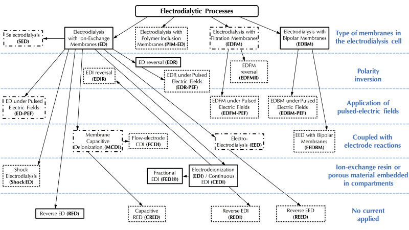
), technologies for which scale-up is underway.
Figure 2
Figure 2
Forecast sales (in number of conventional electrodialysis Units) and revenues (in million US dollars) by countries for 2020.
Figure 3
Figure 3
Evolution of the number of electrodialytic system manufacturers around the World from 1970 to 2020.
Figure 4
Figure 4
Schematic ion concentration profiles in the diffusion boundary layers (DBL) close to a cation-exchange membrane under an electric field, under the limiting current density, and the different mass transfer mechanisms involved in cation migration (Adapted from Bazinet and Castaigne [11]).
Figure 5
Figure 5
Steps in concentration polarization phenomenon at membrane interface during electrodialysis: (a) formation of concentration gradients, (b) reaching the limiting current density and, (c) overpassing the limiting current density and irreversible water dissociation. CEM: cation-exchange membrane; AEM: anion-exchange membrane; δ1: diluate boundary layer; δ2: concentrate boundary layer; CH+: concentration in H+ and COH: concentration in OH (Adapted from Bazinet [22]).
Figure 6
Figure 6
Interferograms of a 1.0 × 10⁻² mol/L sodium chloride solution in the diluate compartment of an ED cell at different current densities (a) 0 A/m2, (b) 18.5 A/m2, (c) 59.7 A/m2 and (d) 126.0 A/m2. Experimental conditions: flow rate of 1.26 × 10⁻³ m/s, intermembrane distance of 1.5 × 10⁻³ m, coordinate in the direction of solution feed 1.1 × 10⁻² m (with permission from Vasil’eva et al. [20]). AEM: Anion-exchange membrane; CEM: Cation-exchange membrane.
Figure 7
Figure 7
Typical current-voltage curve for an ion-exchange membrane and value of the limiting current (adapted from Bazinet and Castaigne [11]).
Figure 8
Figure 8
Determination of the reciprocal limiting current value by the method of Cowan and Brown [41].
Figure 9
Figure 9
Schematic concentration profiles of counter-ions (solid line) and co-ions (double dashed line) in the double boundary layer (DBL, thickness δ) as a function of the current density (dI) applied. SCR: Space charge region; ESCR: extended space charge region (non-equilibrium part); QSCR: quasi-equilibrium part of SCR (Adapted from Nikonenko et al. [21,51]).
Figure 10
Figure 10
Occurrence of electroconvective vortices at membrane interface due to electroosmosis of the second kind (a) as currently accepted (adapted from Nikonenko et al. [21]) and (b) hypothetic, taking into account the ion hydration shell.
Figure 11
Figure 11
Typical current-voltage curve, appearance of electroconvective vortices and intensity of water molecule dissociation (Adapted from Bazinet and Castaigne [11]).
Figure 12
Figure 12
Principle of pulsed electric field (PEF) and effect on concentration polarisation. CEM: cation-exchange membrane; DBL: diffusion boundary layer.
Figure 13
Figure 13
Schematic representation of the studied surface area comprised in the eight PEF conditions tested. Each condition is represented by a table including in the first row: its process duration (in h), its final electrical resistance reduction from the CC application results reported by Dufton et al. [113] (in %) and its relative energy consumption (in Wh/g of lactic acid removed). The second row includes the demineralization rates of calcium, magnesium and sodium (in %), while the third row report the amount of scaling on the AEMs (in g/100 g of dry membrane). The shades of grey represent the position of the condition among the others: the lighter the grey, the better the result in term of acid whey treatment (adapted from Dufton et al. [83]).
Figure 14
Figure 14
Two-dimensional contour plots of relative energy consumption (Wh/1000 C) as a function of pulse and pause durations for (a) demineralization of model salt solution (adapted from [66,110,111,112]; (b) demineralization/lactic acid recovery of acid whey (adapted from [83,113] and (c) demineralization of polymer-flooded produced water (adapted from Sosa-Fernandez et al. [84]. r = pulse duration/pause duration ratio.
Figure 15
Figure 15
Impact of frequency (logarithmic scale) on the demineralization rate (in %). Data were obtained from studies reported in the literature and working with different conditions and solutions: model salt solutions [110,111,112,121], acid whey [83,113], sweet whey [64], polymer flooding produced water [84].
Figure 16
Figure 16
Principle of electrodialysis metathesis. CEM: cation-exchange membrane; AEM: anion-exchange membrane; A, A’: anions; C+, C’+: cations.
Figure 17
Figure 17
Principle of selectrodialysis. CEM: cation-exchange membrane; AEM: anion-exchange membrane; MVA: monovalent selective anion exchange membrane; A, A’2−: anions; C+: cations.
Figure 18
Figure 18
Principle of electro-electrodialysis applied to iodine-sulfur process for hydrogen iodide concentration. CEM: cation-exchange membrane.
Figure 19
Figure 19
Principle of flow-electrode capacitive deionization. CEM: cation-exchange membrane; AEM: anion-exchange membrane; A: anions; C+: cations.
Figure 20
Figure 20
(a) Principle of continuous EDI (CEDI) and (b) current regimes in CEDI and ED (adapted from Hakim et al. [205]). CEM: cation-exchange membrane; AEM: anion-exchange membrane; IX: ion-exchange; A: anions; C+: cations.
Figure 21
Figure 21
Principle of shock ED. CEM: cation-exchange membrane; A: anions; C+: cations.
Figure 22
Figure 22
Principle of EDFM using a cationic configuration. CEM: cation-exchange membrane; FM: filtration membrane, A: anions; C+: cations; M, M+: charged macromolecules.
Figure 23
Figure 23
Principle of reverse ED. CEM: cation-exchange membrane; AEM: anion-exchange membrane; HSS: high-salinity stream; LSS: low-salinity stream.
Figure 24
Figure 24
Theoretical PFED strategy (adapted from Campione et al. [10]). RED: reverse electrodialysis; SED: selectrodialysis; CEDI: continuous deionization.
Figure 25
Figure 25
Wastewater treatment and water purification for zero liquid discharge (ZLD) by forward osmosis (FO) osmotic membrane bioreactor (OMBR)-ED (reprint with permission from Lu and He [307]. Copyright (2015) American Chemical Society). OMBR: osmotic membrane bioreactor; ED: electrodialysis; RO: reverse osmosis.
Figure 26
Figure 26
Strategy for struvite production from sea water and wastewater (adapted from Gao et al. [324]). SED: selectrodialysis, EDBM: electrodialysis with bipolar membranes; CEDI: continuous deionization; MCDI: membrane capacitive deionization.
Figure 27
Figure 27
Eco-efficient milk processing by EDBM-UF for casein production (adapted from Mikhaylin et al. [335]). UF: ultrafiltration; BM: bipolar membrane; CEM: cation-exchange membrane.

References

    1. World Health Organization . Progress on Household Drinking Water, Sanitation and Hygiene 2000–2017: Special Focus on Inequalities. World Health Organization; New York, NY, USA: 2019.
    1. World Health Organization . Food Safety: Fact Sheet No. 399. World Health Organization; Geneva, Swizterland: 2015.
    1. World Health Organization Environment and Health in Developing Countries. [(accessed on 17 July 2020)]; Available online: https://www.who.int/heli/risks/ehindevcoun/en/
    1. Van der Bruggen B. Chapter 7—Ion-exchange membrane systems—Electrodialysis and other electromembrane processes. In: Luis P., editor. Fundamental Modelling of Membrane Systems. Elsevier; Amsterdam, The Netherlands: 2018. pp. 251–300.
    1. Bazinet L., Firdaous L. Separation of bioactive peptides by membrane processes: Technologies and devices. Recent Pat. Biotechnol. 2013;7:9–27. doi: 10.2174/1872208311307010003. - DOI - PubMed

LinkOut - more resources