. 2019 Aug 8:1:19.
doi: 10.1186/s42490-019-0019-7. eCollection 2019.

Telemetry-controlled simultaneous stimulation-and-recording device (SRD) to study interhemispheric cortical circuits in rat primary somatosensory (SI) cortex

Affiliations

Telemetry-controlled simultaneous stimulation-and-recording device (SRD) to study interhemispheric cortical circuits in rat primary somatosensory (SI) cortex

John T Ramshur et al. BMC Biomed Eng. .

Abstract

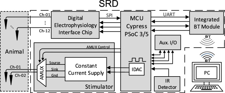
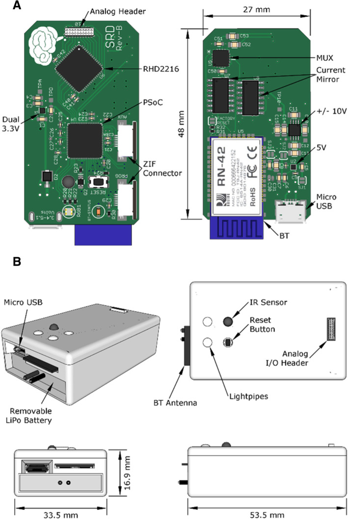
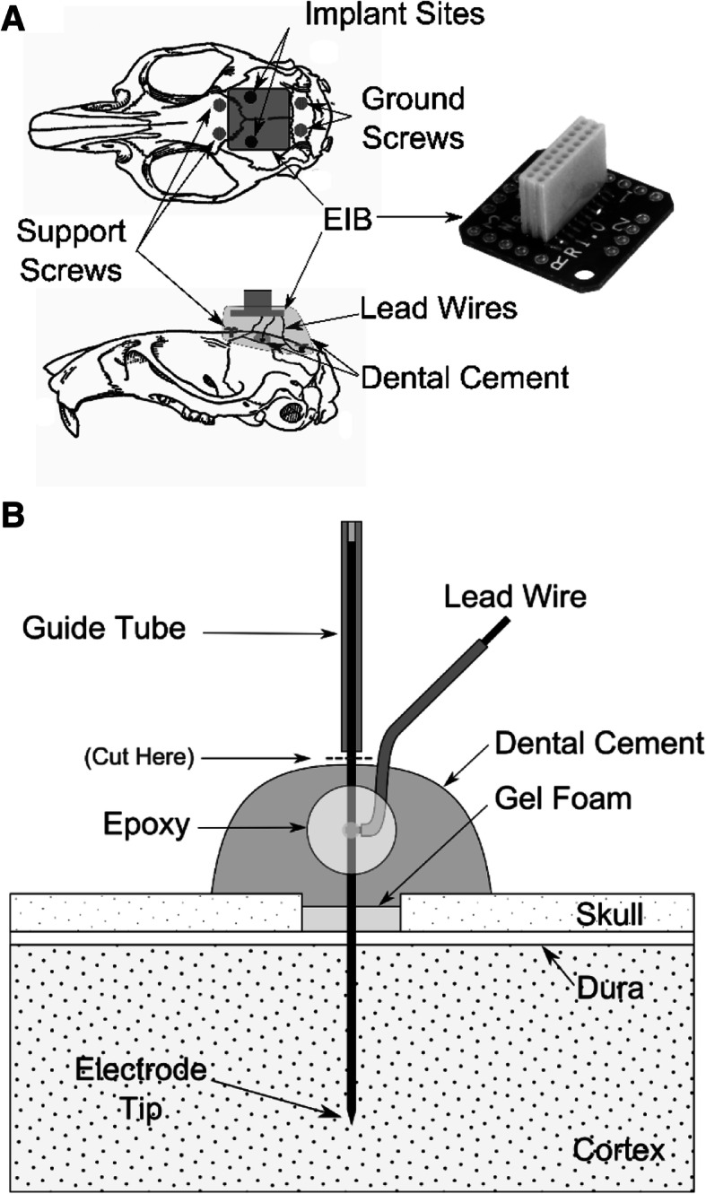
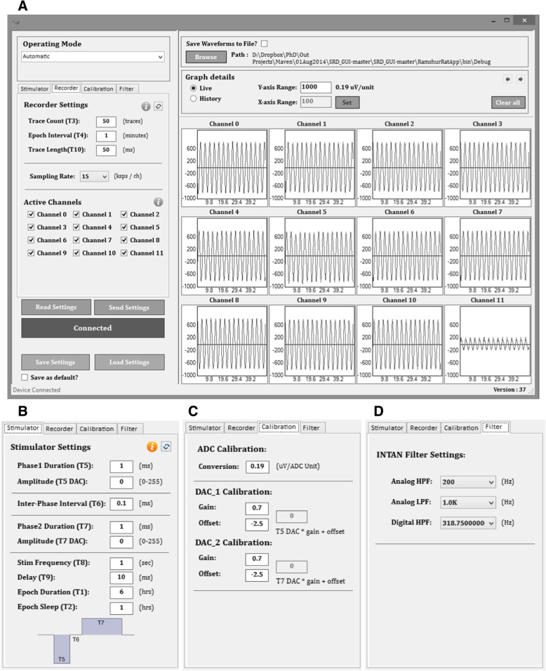
Background: A growing need exists for neuroscience platforms that can perform simultaneous chronic recording and stimulation of neural tissue in animal models in a telemetry-controlled fashion with signal processing for analysis of the chronic recording data and external triggering capability. We describe the system design, testing, evaluation, and implementation of a wireless simultaneous stimulation-and-recording device (SRD) for modulating cortical circuits in physiologically identified sites in primary somatosensory (SI) cortex in awake-behaving and freely-moving rats. The SRD was developed using low-cost electronic components and open-source software. The function of the SRD was assessed by bench and in-vivo testing.

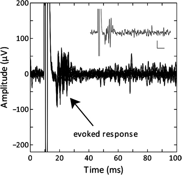
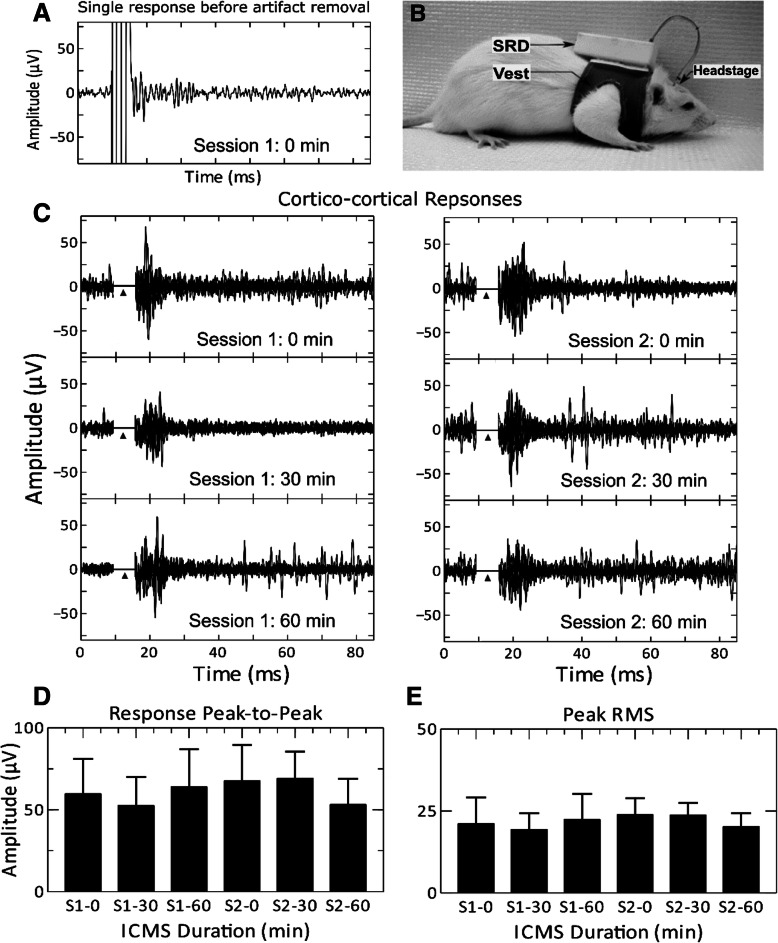
Results: The SRD recorded spontaneous spiking and bursting neuronal activity, evoked responses to programmed intracortical microstimulation (ICMS) delivered internally by the SRD, and evoked responses to external peripheral forelimb stimulation.

Conclusions: The SRD is capable of wireless stimulation and recording on a predetermined schedule or can be wirelessly synchronized with external input as would be required in behavioral testing prior to, during, and following ICMS.

Keywords: Brain-computer interface; Intracortical microstimulation; Primary somatosensory cortex.


Conflict of interest statement

Competing interestsThe authors declare that they have no competing interests.

Figures

Fig. 1
Fig. 1
a Frequency response of simulated (blue) and measured (red) gains for fL = 100 Hz and fH = 1 kHz. Vertical lines represent the desired overall filter bandwidth of 300 Hz − 1 kHz. The horizontal line marks − 3 dB gain. b Frequency response of simulated phase angle. Dashed curves represent frequency responses with the digital high-pass filter (offset removal filter) disabled, and solid curves represent the digital filter–enabled fD = 318 Hz. digital: dig
Fig. 2
Fig. 2
In-vivo examples of pseudophasic (non-symmetric biphasic) (a, c) and symmetric biphasic (b, d) constant current stimuli delivered to rat SI cortex with 100-kΩ platinum-iridium (Pt/Ir) microelectrode. Measured output current (black line) and simultaneously measured voltage drop (gray line) across the tissue/electrode load are shown: a cathodic: 100 μA, 1 ms; anodic: 100 μA, 2 ms; b cathodic: 50 μA, 2 ms; anodic: 60 μA, 2 ms; c cathodic: 30 μA, 1-ms; anodic: 50 μA, 2 ms, and d cathodic/anodic: 100 μA, 2 ms. Inter-pulse intervals are 1 ms (a, c) and 0.2 ms (b, d)
Fig. 3
Fig. 3
A 1-MΩ microelectrode was implanted in SI in the wrist/forearm representation (right hemisphere) and was used to record evoked responses to stimulation of the contralateral wrist/forearm. A total of 10 evoked responses were recorded during peripheral stimulation (100 μA) of the contralateral forelimb on day 21. Inset: Single trace recorded at the same cortical location. Legend axes represent 30 μV and 10 ms
Fig. 4
Fig. 4
a Cortico-cortical evoked response to ICMS delivered to the wrist representation at 8 days post-implantation. b Photograph of rat wearing the SRD system. The SRD was fixed to the vest with Velcro and connected to the electrode interface board (EIB) on the headstage using a wire interconnect. Cortico-cortical evoked responses to ICMS delivered to the wrist representation at 8 days post-implantation are shown in (c). Each of the six rows of traces represents cortico-cortical evoked responses seen during two 60-min sessions of chronic ICMS (100 μA). Each plot shows 10 traces. Triangle (▲) indicates location of stimulus artifact which was removed after data was transmitted to the host PC. Artifact was replaced with a value of zero if rectified trace sample was greater than the maximum rectified amplitude of the post-stimulus evoked response. d Mean peak-to-peak signal amplitudes for each time point in (b) are shown with error bars representing one standard deviation. e Mean instantaneous RMS peaks for each time point in (b) are shown with error bars representing one standard deviation
Fig. 5
Fig. 5
SRD system overview showing interconnections between the microcontroller unit (MCU) with on-board current-mode digital-to-analog converters (IDAC), universal asynchronous receiver/transmitter (UART), serial peripheral interface (SPI), Bluetooth (BT) module, host PC, stimulator with analog multiplexor (AMUX), digital electrophysiology interface chip (recorder), auxiliary input/output (Aux. I/O), infrared (IR) detector, and electrodes (e.g. Ch-01, Ch-02) within animal tissue. Figure modified from [21].© 2014 IEEE. Reprinted, with permission, from IEEE Proceedings
Fig. 6
Fig. 6
a PCB component layout of top and bottom sides of the SRD. b 3D model of SRD enclosure with several key features highlighted including the exposed micro USB connector, removable battery, exposed BT antenna, light pipes, IR sensor, recessed reset button, and analog header. The enclosure lid is held onto the primary enclosure body by four pair of 2 mm × 2 mm cylindrical neodymium magnets
Fig. 7
Fig. 7
a Illustration of SRD headstage with EIB, approximate locations of implant sites, screws, lead wires, and encapsulating dental cement. b Illustration of chronic electrode implanted into cortex. Electrode is secured to the skull by dental cement. After dental cement was cured, the remaining electrode shaft and guide tube were cut just above the cured cement
Fig. 8
Fig. 8
a Screenshot of the GUI showing live streaming of a sine wave to all SRD input channels with the Recorder settings tab selected. The sections of the GUI are operating mode (top left), stimulator, recorder, calibration, and filter settings tabs (middle left), buttons for connecting to the SRD, sending/receiving settings to/from SRD, and saving/loading settings from a file saved to the PC (bottom left), options for saving waveforms to file (top right), options for viewing live or previous waveform files (middle right), and graphs of all 12 available channels with sinusoidal waveforms shown for demonstration purposes (bottom right). Recorder settings include the trace count (number of traces captured during each recording epoch used in automatic mode), epoch interval, trace length, sampling rate, and active channels. b Stimulator tab settings include amplitudes, durations, inter-phase interval, frequency, and stimulation delay (relative to start of recording). c Calibration tab settings include ADC calibration and stimulation calibration gain and offset (assumes linear calibration). d Filter tab settings include − 3 dB cutoff frequencies for fL, fH, and fD

Similar articles

Cited by

References

    1. Muller J, Bakkum DJ, Hierlemann A. Sub-millisecond closed-loop feedback stimulation between arbitrary sets of individual neurons. Front Neural Circuits. 2012;6:121. - PMC - PubMed
    1. Fan D, Rich D, Holtzman T, Ruther P, Dalley JW, Lopez A, et al. A wireless multi-channel recording system for freely behaving mice and rats. PLoS One. 2011;6(7):e22033. doi: 10.1371/journal.pone.0022033. - DOI - PMC - PubMed
    1. Zanos S, Richardson AG, Shupe L, Miles FP, Fetz EE. The Neurochip-2: an autonomous head-fixed computer for recording and stimulating in freely behaving monkeys. IEEE Trans Neural Syst Rehabil Eng. 2011;19(4):427–435. doi: 10.1109/TNSRE.2011.2158007. - DOI - PMC - PubMed
    1. Harrison RR, Fotowat H, Chan R, Kier RJ, Olberg R, Leonardo A, et al. Wireless neural/EMG telemetry Systems for Small Freely Moving Animals. IEEE Trans Biomed Circuits Syst. 2011;5(2):103–111. doi: 10.1109/TBCAS.2011.2131140. - DOI - PubMed
    1. Ye X, Wang P, Liu J, Zhang S, Jiang J, Wang Q, et al. A portable telemetry system for brain stimulation and neuronal activity recording in freely behaving small animals. J Neurosci Methods. 2008;174(2):186–193. doi: 10.1016/j.jneumeth.2008.07.002. - DOI - PubMed

LinkOut - more resources