Review
. 2020 Sep 11;13(18):4033.
doi: 10.3390/ma13184033.

Magnetoelectrics: Three Centuries of Research Heading towards the 4.0 Industrial Revolution

Affiliations
Review

Magnetoelectrics: Three Centuries of Research Heading towards the 4.0 Industrial Revolution

Nélson Pereira et al. Materials (Basel). .

Abstract

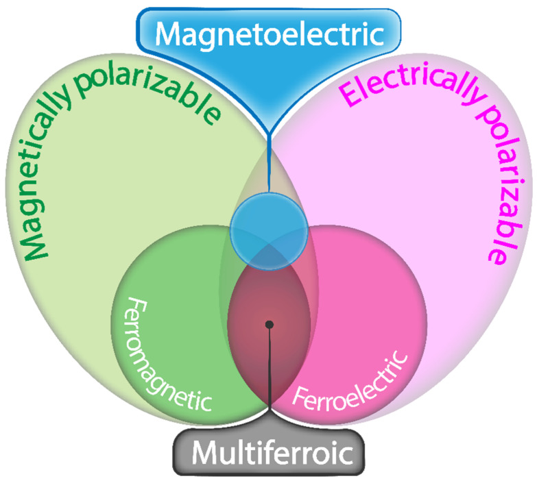
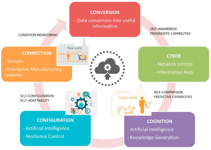
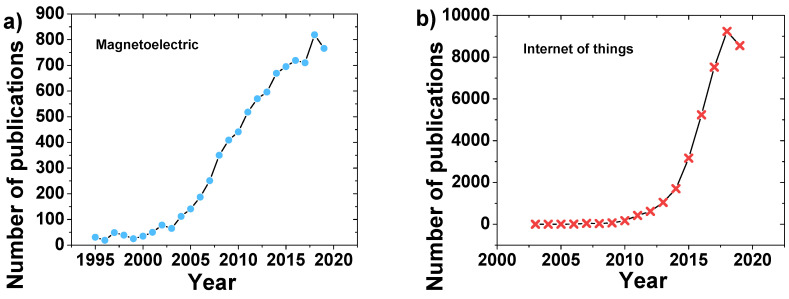
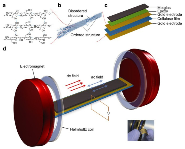
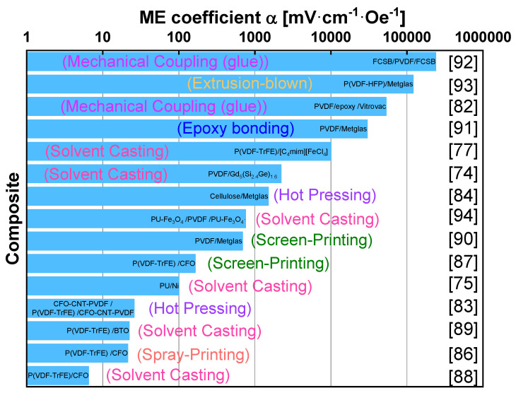
Magnetoelectric (ME) materials composed of magnetostrictive and piezoelectric phases have been the subject of decades of research due to their versatility and unique capability to couple the magnetic and electric properties of the matter. While these materials are often studied from a fundamental point of view, the 4.0 revolution (automation of traditional manufacturing and industrial practices, using modern smart technology) and the Internet of Things (IoT) context allows the perfect conditions for this type of materials being effectively/finally implemented in a variety of advanced applications. This review starts in the era of Rontgen and Curie and ends up in the present day, highlighting challenges/directions for the time to come. The main materials, configurations, ME coefficients, and processing techniques are reported.

Keywords: 4.0 industrial revolution; IoT; magnetoelectric; magnetostrictive; multiferroic; piezoelectric.


Conflict of interest statement

The authors declare no conflict of interest.

Figures

Figure 1
Figure 1
The relation between multiferroic and ME materials, adapted from [1].
Figure 2
Figure 2
The schematic illustration of three bulk composites with different connectivity: (a) (0–3) particulate composite; (b) (2–2) laminate composite; (c) (1–3) fiber/rod composite. Reproduced with permission from [2].
Figure 3
Figure 3
The model for Industry 4.0. Reproduced with permission from [15].
Figure 4
Figure 4
The publications per year according to the Web of Science database (7/2020) with the key words (a) magnetoelectric; and (b) internet of things [20].
Figure 5
Figure 5
(a) Magnetic field dependence of the magnetization for the Bi0.5Nd0.5FeO3 solid solution. ME coupling coefficient variation with: (b) static magnetic field HDC and (c) frequency f of sinusoidal magnetic field HAC for Bi0.5Nd0.5FeO3 sample. Reproduced with permission from [23].
Figure 6
Figure 6
(a) The schematic representation of the experimental conditions; and (b) M–E coupling coefficient versus applied magnetic field measured in both in-plane magnetized-out of plane polarized configuration (L–T) and out of plane magnetized-out of plane polarized (T–T) modes. Reproduced with permission from [25]. (c) ME coefficient for a HAC = 3 Oe at 993 Hz [26]. (d) MEP (H) hysteresis loops displayed at 300 K, showing the variations of the ME coefficient as a function of the applied magnetic field for of BDFO (red) and BFO (black). Reproduced with permission from [28].
Figure 7
Figure 7
Some representative single-phase materials and their corresponding ME voltage coefficient and fabrication process.
Figure 8
Figure 8
(a) The configuration of laminated Terfenol-D/PZT/Ni composite cantilever; (b) magnetization of Terfenol-D with bias field at different orientation angles. Reproduced with permission from [56].
Figure 9
Figure 9
(a) The sketch of the structure of ME composites with microwires; (b) Hysteresis loops of individual microwires with composition of Fe77.5B15Si7.5 in as-cast state (S1) and after different treatments (S2–S5: As-cast and then annealed (S2); As-cast and glass-coat removed (S3); As-cast, annealed, and then glass-coat removed (S4); As-cast, glass-coat removed, and then annealed) [61].
Figure 10
Figure 10
Some representative ceramic-based ME materials together with the ME coefficients, processing techniques, and main application areas.
Figure 11
Figure 11
The MI nanocomposite and experimental set-up for the measurement of the MI effect. (a) Schematic representation of the [C4mim] + cation. (b) Schematic representation of the [FeCl4]—anion. (c) Illustration of the P(VDF-TrFE) monomer structure. (d) Profile chart of the MI composite. (e) Schematic view of the system for MI voltage measurement. Reproduced with permission from [77].
Figure 12
Figure 12
The schematic representation of the Vitrovac/Epoxy/PVDF composite (a); optimization process (b) and ME response (c) pave the way for its incorporation into technological applications such as magnetic sensors (d). Reproduced with permission from [82].
Figure 13
Figure 13
(a) The scheme of cellulose crystal II; (b) Illustration of cellulose fibril alignment at the cross-section of cellulose film; (c) Schematic of cellulose-based ME laminate structure; (d) Schematic view of the bulk system for ME voltage measurement. Reproduced with permission from [84].
Figure 14
Figure 14
Some representative polymer-based ME materials, and their respective ME voltage coefficient.
Figure 15
Figure 15
(a) The theoretical simulation of the AC magnetic field (in T) generated for a printed coil with a width of 750 and 250 μm spacing, 15 turns and a current (I) = 0.02 A. (b) Schematic representation of the printing process of the coils. (c) Coil printing detail obtained with a digital microscope. Reproduced with permission from [101].
Figure 16
Figure 16
(a) The resonance frequency of the ME laminate as a function of applied HDC, (b) The induced voltage as a function of applied HDC and excitation frequency, (c) The M-H loop of the ME laminate with voltages of 0 V and 600 V applied to the piezoelectric crystal. ΔM as a function of external HDC is also given on the right. The inset shows the schematic of the ME heterostructure. Reproduced with permission from [104].
Figure 17
Figure 17
(a) The ME transducer experimental test setup diagram. (b) Metglas-PVDF open circuit voltage vs. frequency. Reproduced with permission from [107].

References

    1. Eerenstein W., Mathur N.D., Scott J.F. Multiferroic and magnetoelectric materials. Nature. 2006;442:759–765. doi: 10.1038/nature05023. - DOI - PubMed
    1. Nan C.-W., Bichurin M., Dong S., Viehland D., Srinivasan G. Multiferroic magnetoelectric composites: Historical perspective, status, and future directions. J. Appl. Phys. 2008;103:031101. doi: 10.1063/1.2836410. - DOI
    1. Röntgen W.C. Ueber die durch Bewegung eines im homogenen electrischen Felde befindlichen Dielectricums hervorgerufene electrodynamische Kraft. Ann. Phys. 1888;271:264–270. doi: 10.1002/andp.18882711003. - DOI
    1. Curie P.J.J.d.P. Sur la symétrie des phénomènes physiques: Symétrie d’un champ électrique et d’un champ magnétique. J. Phys. 1894;3:393–415.
    1. Dzyaloshinskii I.E. On the magneto-electrical effects in antiferromagnets. Soviet Phys. JETP. 1960;10:628–629.

LinkOut - more resources