. 2020 Sep 13;11(9):851.
doi: 10.3390/mi11090851.

Low Cost AIP Design in 5G Flexible Antenna Phase Array System Application

Affiliations

Low Cost AIP Design in 5G Flexible Antenna Phase Array System Application

Wei-Shin Tung et al. Micromachines (Basel). .

Abstract

In this paper, a low cost 28 GHz Antenna-in-Package (AIP) for a 5G communication system is designed and investigated. The antenna is implemented on a low-cost FR4 substrate with a phase shift control integrated circuit, AnokiWave phasor integrated circuit (IC). The unit cell where the array antenna and IC are integrated in the same plate constructs a flexible phase array system. Using the AIP unit cell, the desired antenna array can be created, such as 2 × 8, 8 × 8 or 2 × 64 arrays. The study design proposed in this study is a 2 × 2 unit cell structure with dimensions of 18 mm × 14 mm × 0.71 mm. The return loss at a 10 dB bandwidth is 26.5-29.5 GHz while the peak gain of the unit cell achieved 14.4 dBi at 28 GHz.

Keywords: 28 GHz antenna; antenna in package; phase array antenna.


Conflict of interest statement

The authors declare no conflict of interest.

Figures

Figure 1
Figure 1
The structure of the patch antenna with air cavity.
Figure 2
Figure 2
(a) Top view and (b) cross section view of the patch antenna.
Figure 3
Figure 3
(a) The return loss and (b) the radiation efficiency of the patch antenna.
Figure 4
Figure 4
Beam steering/scanning antenna array [24].
Figure 5
Figure 5
The structure of proposed array antenna with phasor IC.
Figure 6
Figure 6
Directivity as a function of antenna spacing for a broadside array of isotropic elements [25].
Figure 7
Figure 7
Four (4) ports return loss of the simulation.
Figure 8
Figure 8
Radiation pattern of the simulation (X Cut).
Figure 9
Figure 9
Radiation pattern of the simulation (Y Cut).
Figure 10
Figure 10
Antenna peak gain.
Figure 11
Figure 11
Simulation results of the beam steering pattern at 28 GHz (X-cut).
Figure 12
Figure 12
Simulation results of the beam steering pattern at 28 GHz (Y-cut).
Figure 13
Figure 13
Manufacturing process of the antenna with an air-filled cavity.
Figure 14
Figure 14
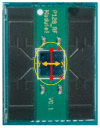
Photograph of the array antenna (2 × 2).
Figure 15
Figure 15
Comparison of the simulation and empirical results of the return loss of each patch, (a) return loss of Patch1; (b) return loss of Patch2; (c) return loss of Patch3; (d) return loss of Patch4.
Figure 15
Figure 15
Comparison of the simulation and empirical results of the return loss of each patch, (a) return loss of Patch1; (b) return loss of Patch2; (c) return loss of Patch3; (d) return loss of Patch4.
Figure 16
Figure 16
NSI-700S-360 antenna chamber, (a) instrument diagram; (b) equipment setup [26].
Figure 17
Figure 17
Measurement coordinates.
Figure 18
Figure 18
Single patch antenna gain (X-cut).
Figure 19
Figure 19
Single patch antenna gain (Y-cut).
Figure 20
Figure 20
Array antenna (2 × 2) gain measurement results (phase 0/180/180/0, X-cut).
Figure 21
Figure 21
Array antenna (2 × 2) gain measurement results (phase 0/180/180/0, Y-cut).
Figure 22
Figure 22
3D radiation pattern of the array antenna at 28 GHz: (a) simulation result and (b) measurement result (normalized).

References

    1. Ateya A.A., Muthanna A., Gudkova I., Id A.A., Vybornova A., Koucheryavy A. Development of Intelligent Core Network for Tactile Internet and Future Smart Systems. J. Sens. Acuator Netw. 2018;7:1. doi: 10.3390/jsan7010001. - DOI
    1. Szeląg B., Drewnowski J., Łagód G., Majerek D., Dacewicz E., Fatone F. Soft Sensor Application in Identification of the Activated Sludge Bulking Considering the Technological and Economical Aspects of Smart Systems Functioning. Sensors. 2020;20:1941. doi: 10.3390/s20071941. - DOI - PMC - PubMed
    1. Grasso C., Schembra G. A Fleet of MEC UAVs to Extend a 5G Network Slice for Video Monitoring with Low-Latency Constraints. J. Sens. Actuator Netw. 2019;8:3. doi: 10.3390/jsan8010003. - DOI
    1. Patcharamaneepakorn P., Wu S., Wang C.-X., Aggoune E.-H.M., Alwakeel M.M., Ge X., Di Renzo M., Aggoune H. Spectral, Energy, and Economic Efficiency of 5G Multicell Massive MIMO Systems With Generalized Spatial Modulation. IEEE Trans. Veh. Technol. 2016;65:9715–9731. doi: 10.1109/TVT.2016.2526628. - DOI
    1. Patcharamaneepakorn P., Wang C.X., Fu Y., Aggoune E.H.M., Alwakeel M.M., Tao X., Ge X. Quadrature Space-Frequency Index Modulation Communication Systems. IEEE Trans. Commun. 2017;66:3050–3064. doi: 10.1109/TCOMM.2017.2776956. - DOI

LinkOut - more resources