Review

New developments in RiPP discovery, enzymology and engineering

Manuel Montalbán-López et al. Nat Prod Rep. .

Abstract

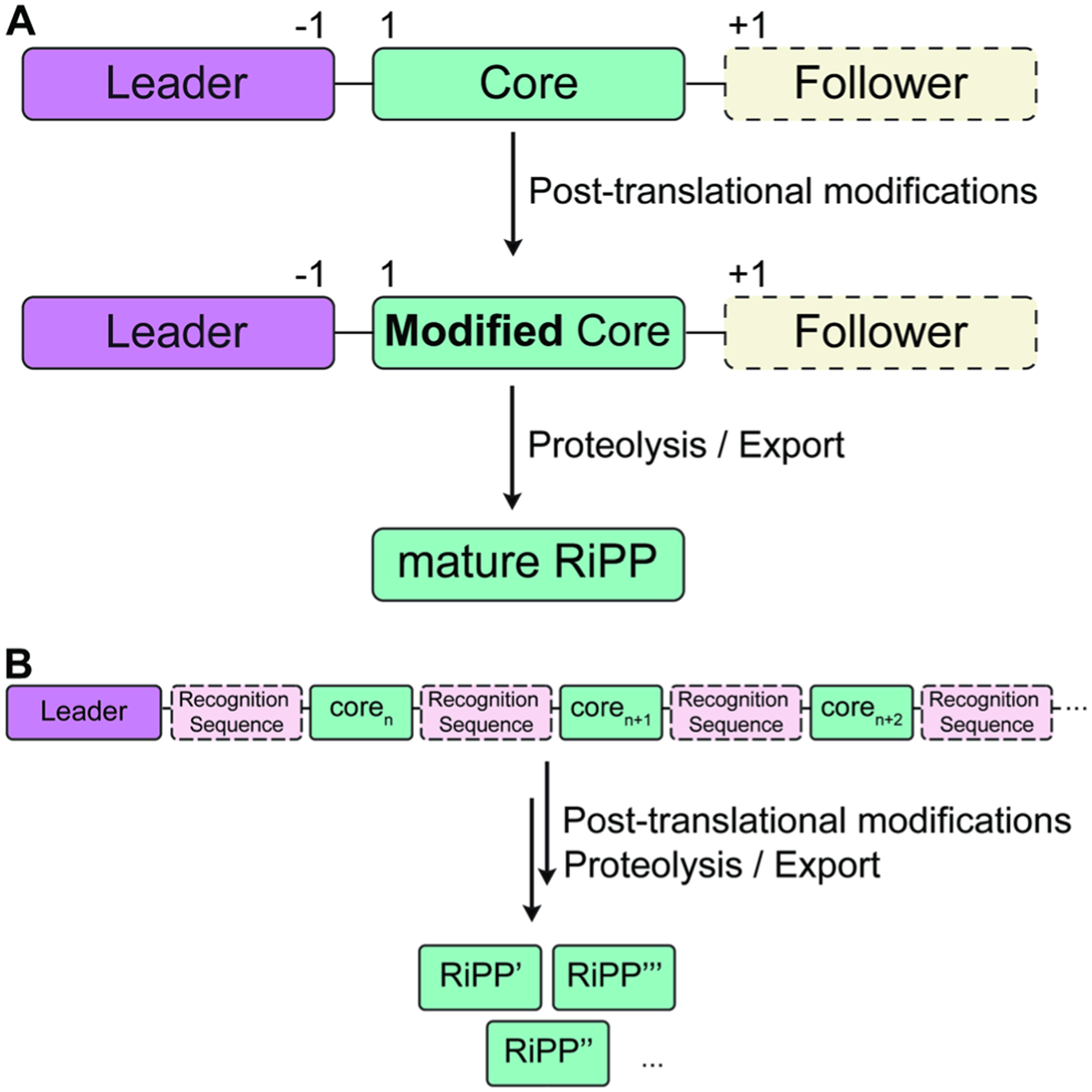
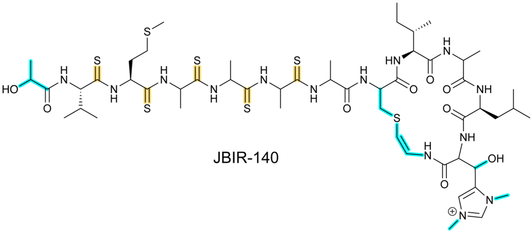
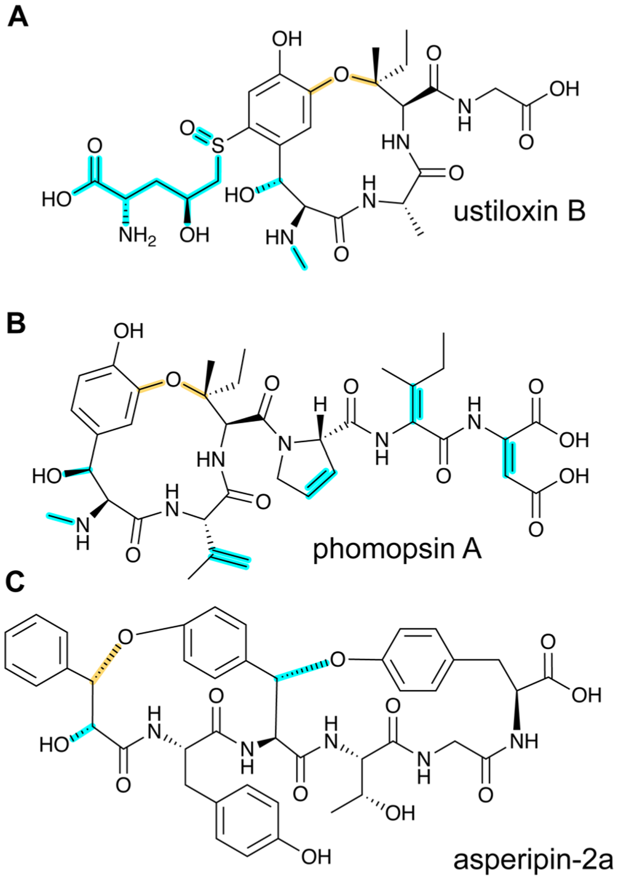
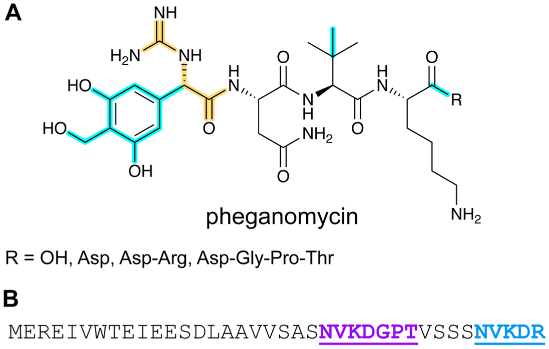
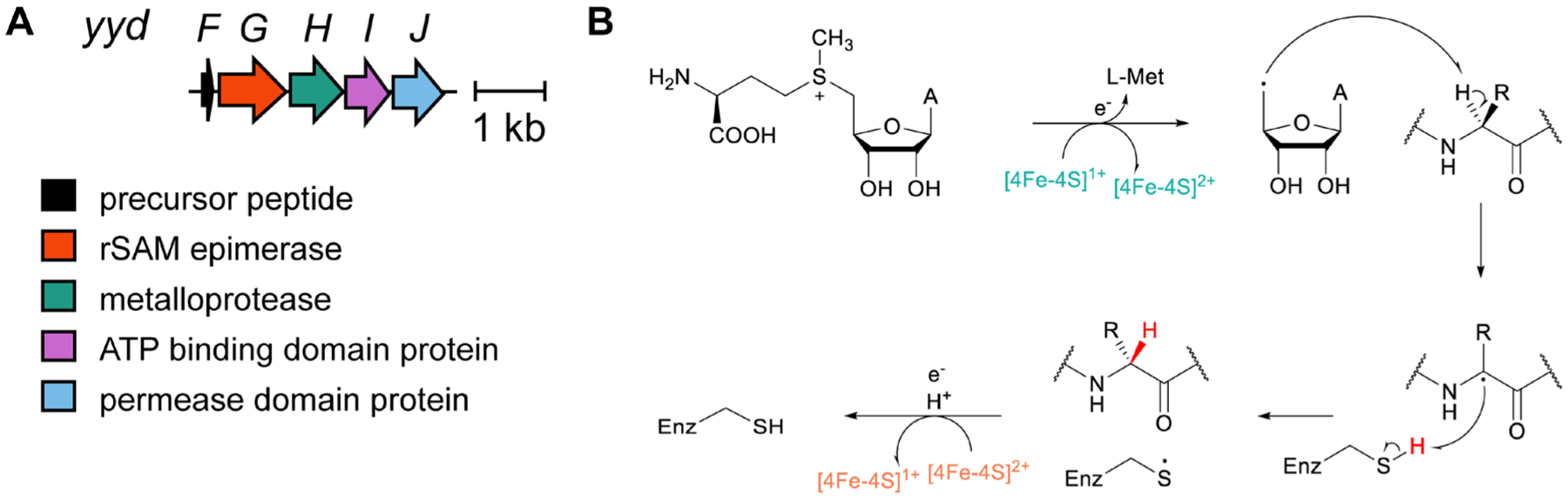
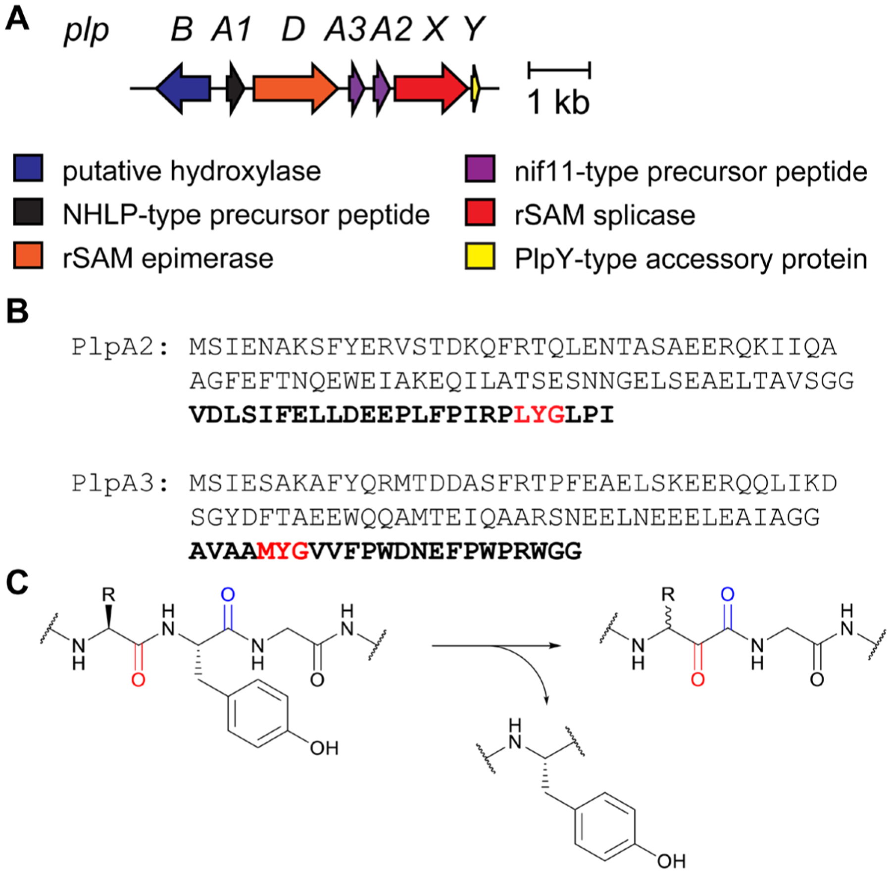
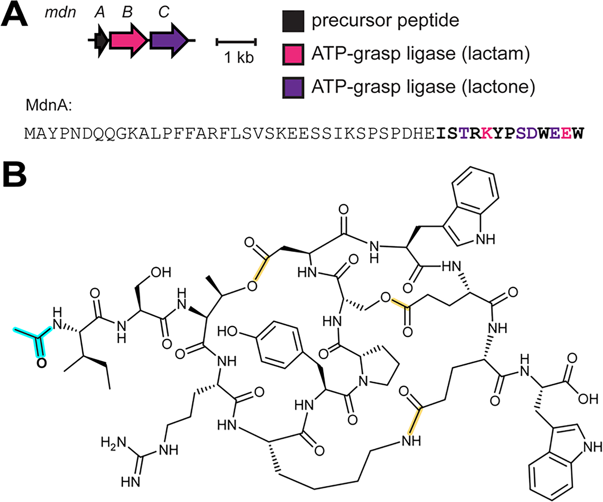
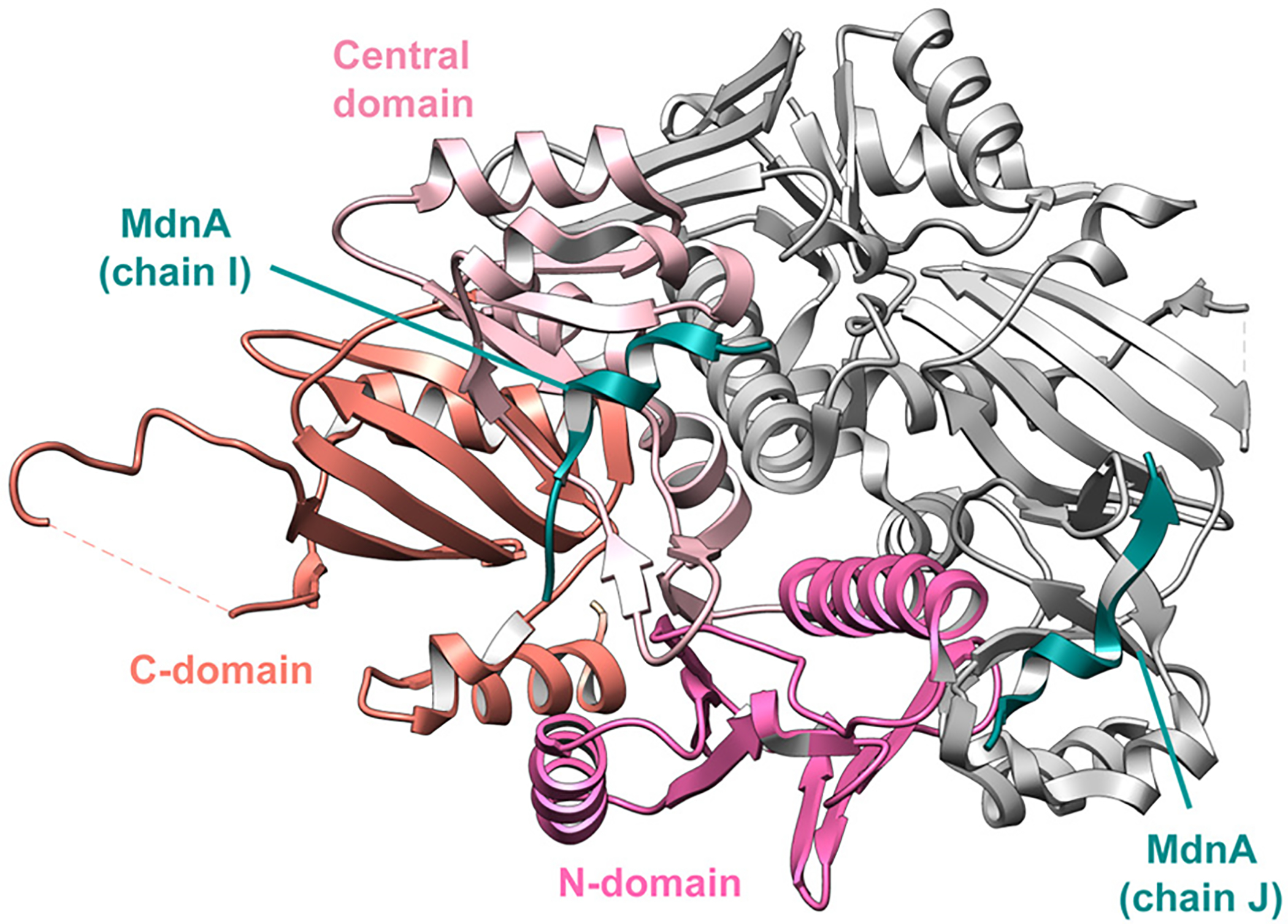
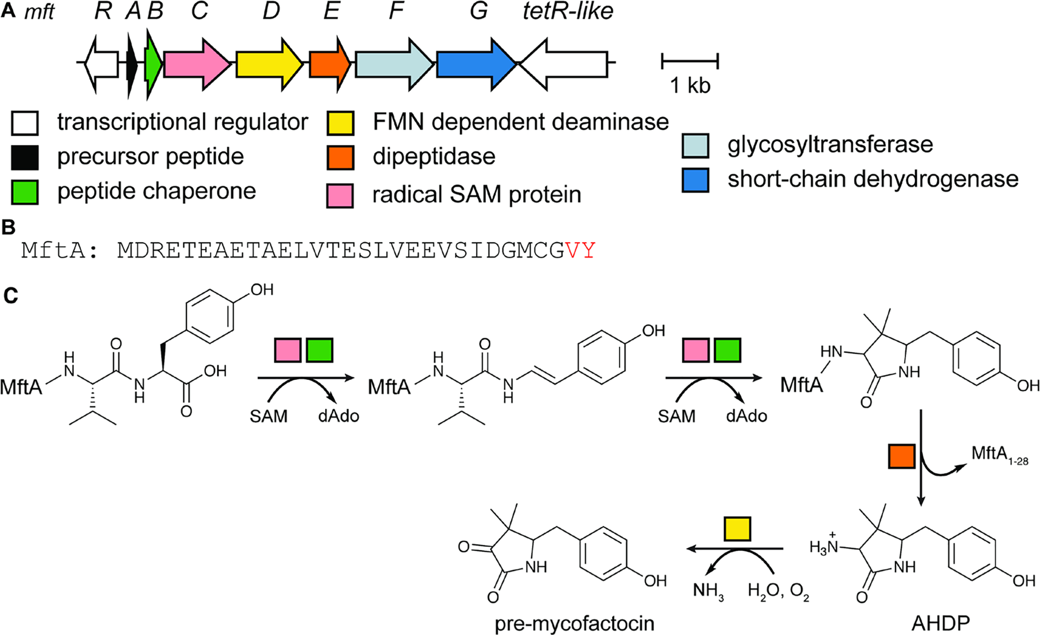
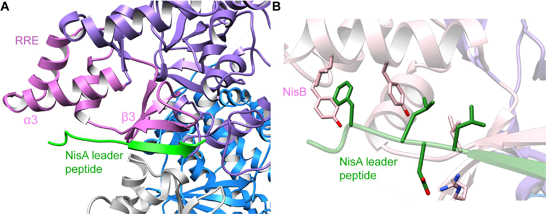
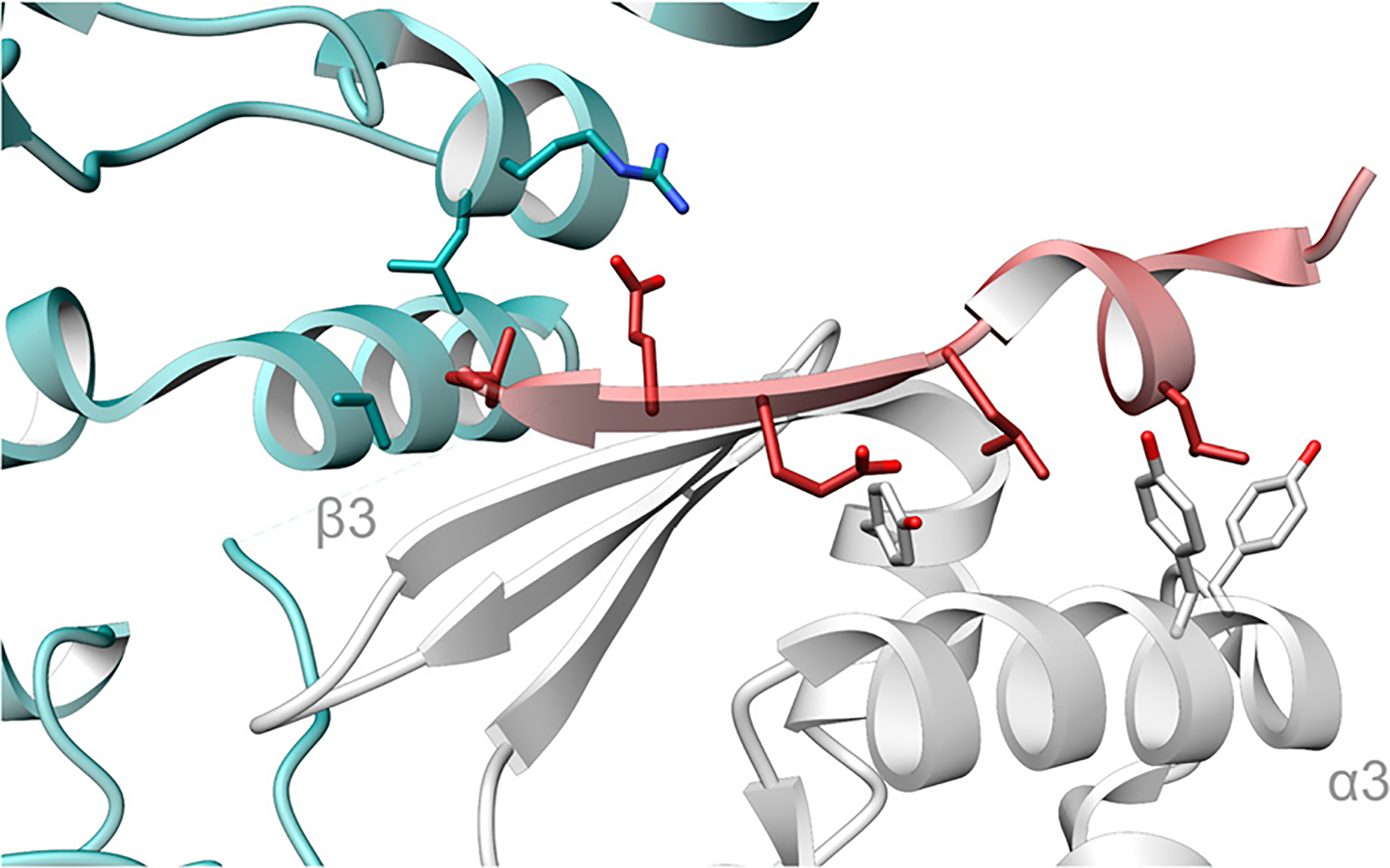
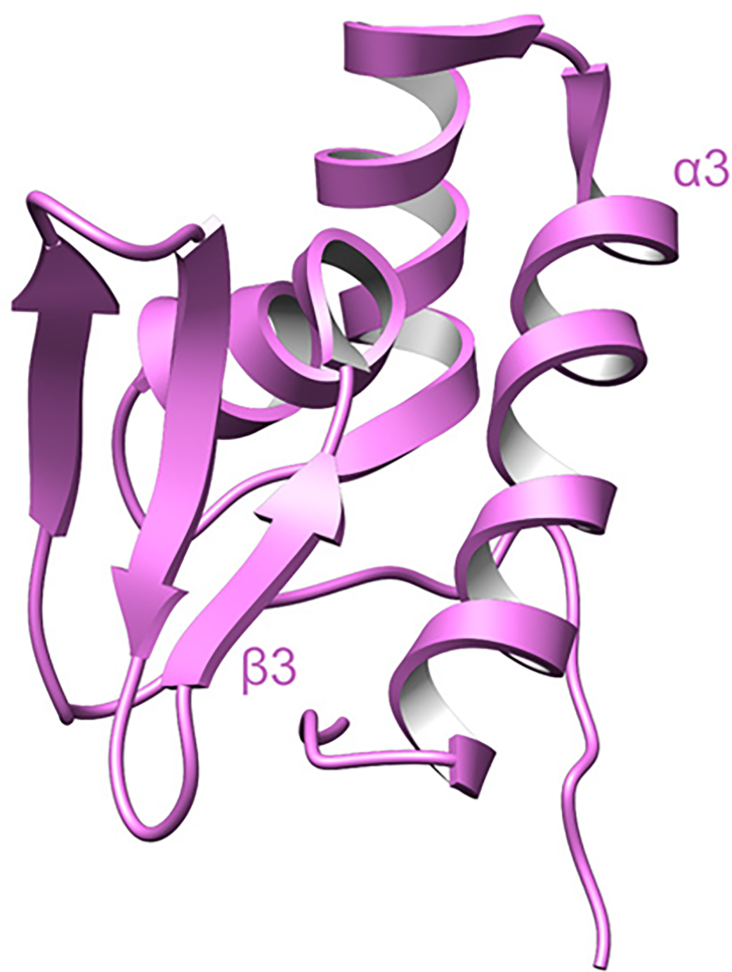
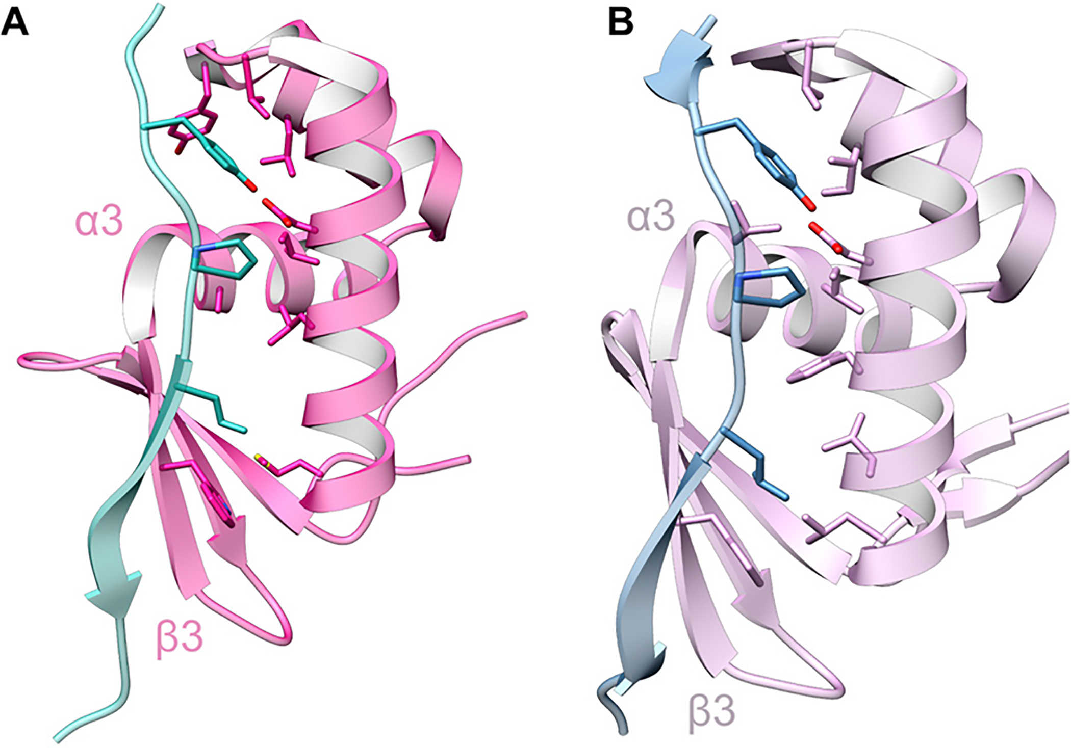
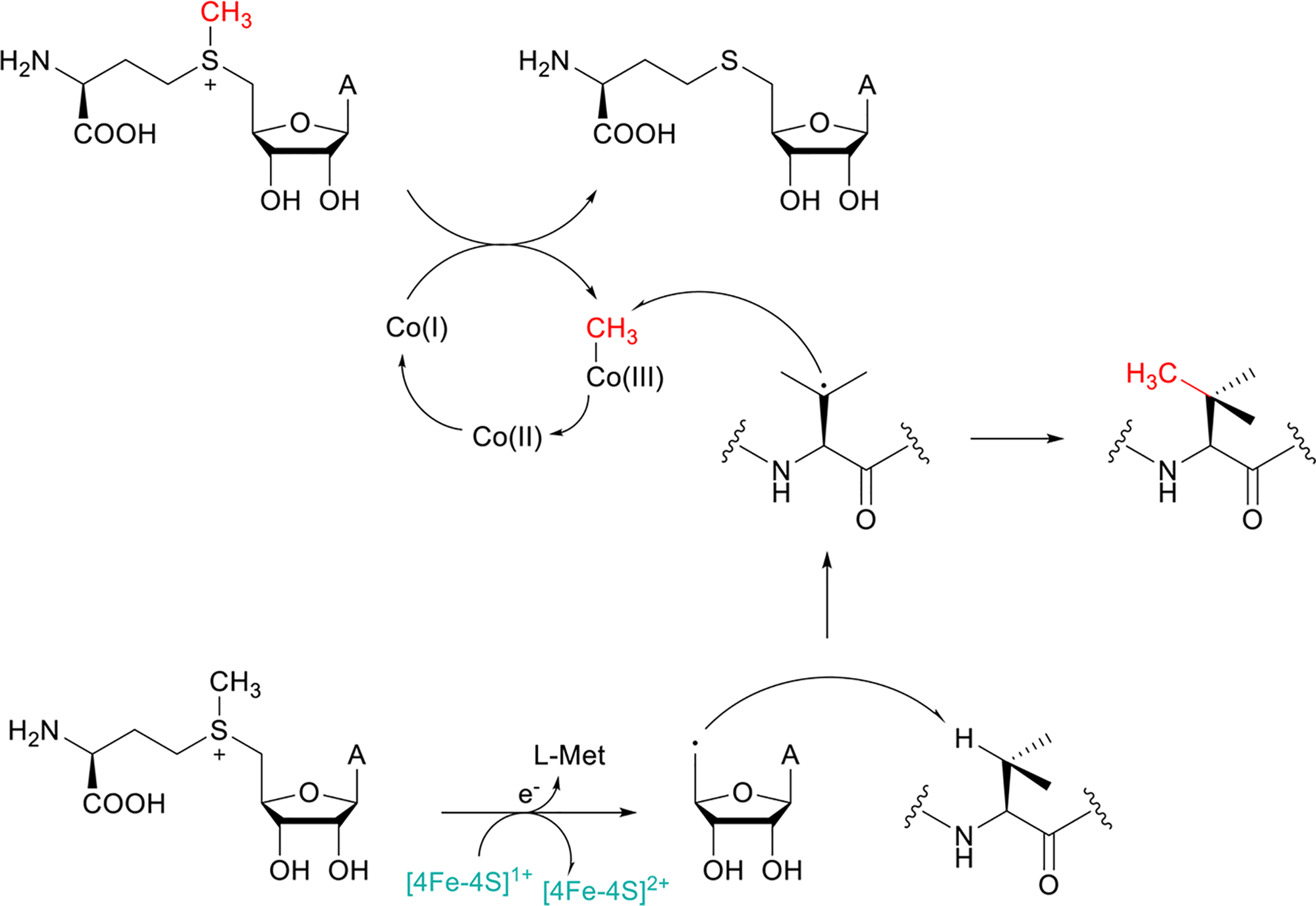
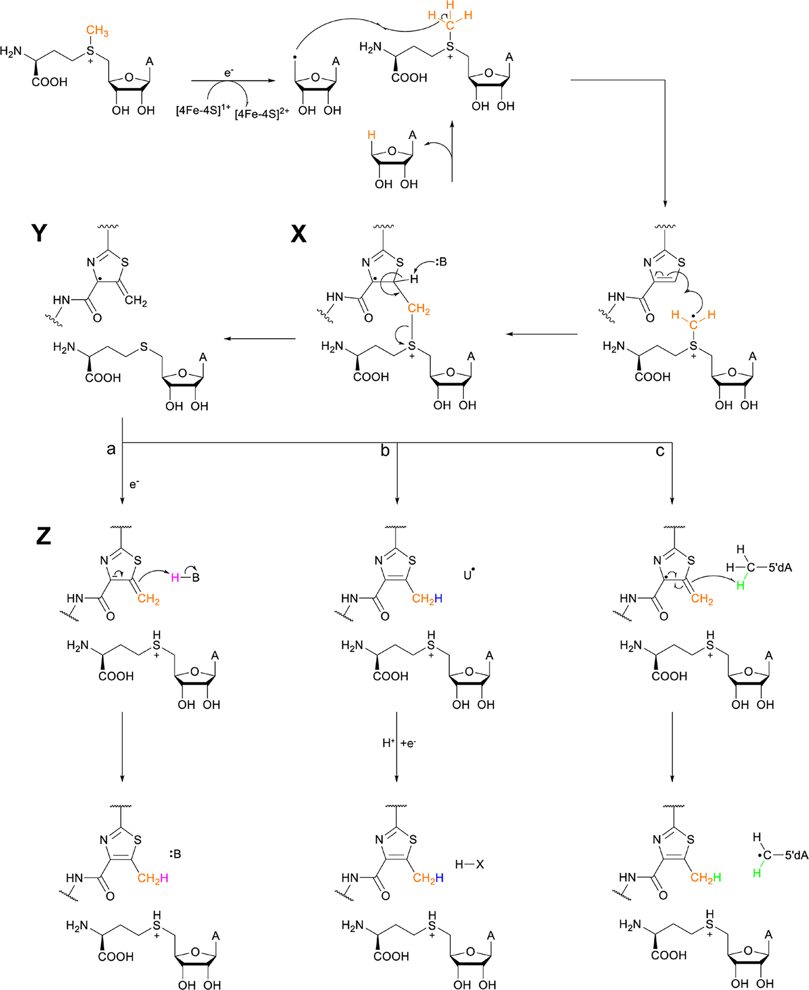
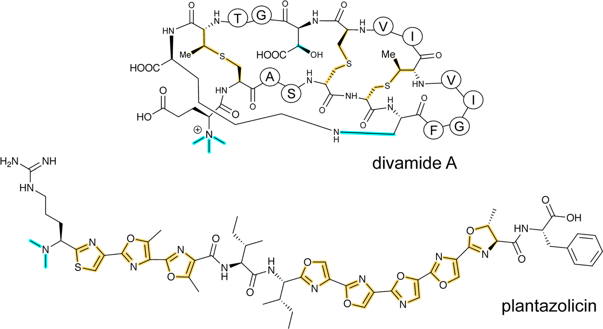
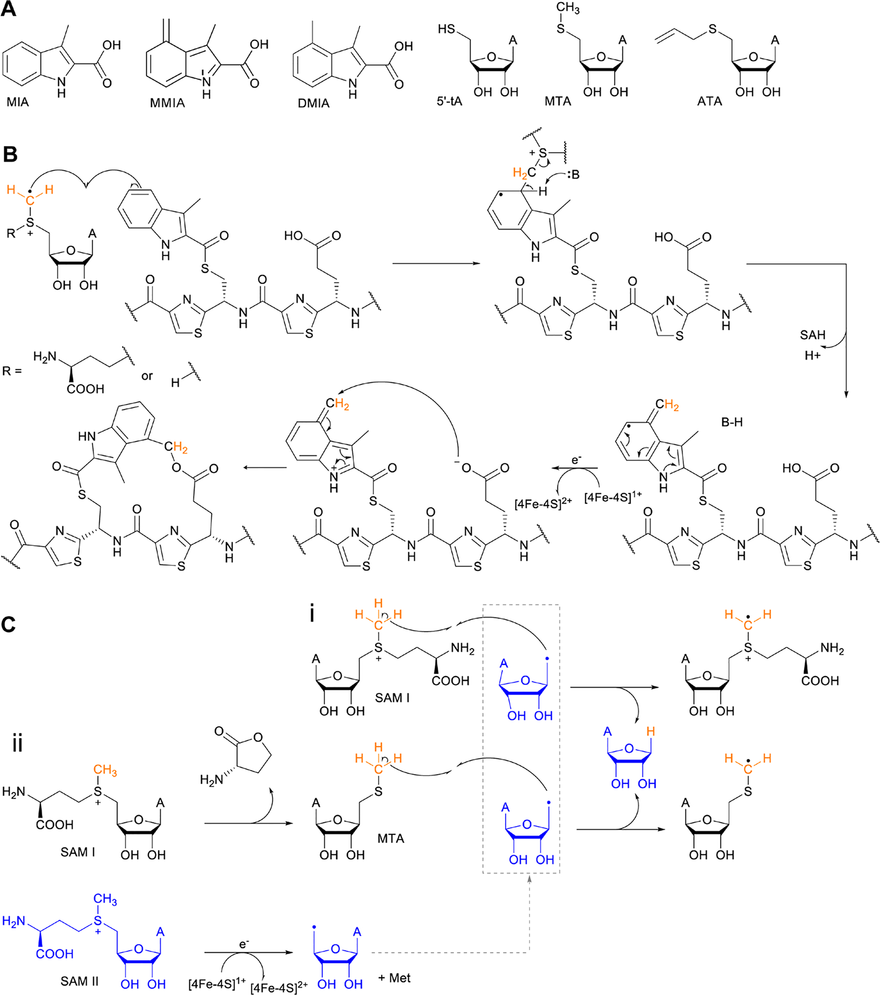
Covering: up to June 2020Ribosomally-synthesized and post-translationally modified peptides (RiPPs) are a large group of natural products. A community-driven review in 2013 described the emerging commonalities in the biosynthesis of RiPPs and the opportunities they offered for bioengineering and genome mining. Since then, the field has seen tremendous advances in understanding of the mechanisms by which nature assembles these compounds, in engineering their biosynthetic machinery for a wide range of applications, and in the discovery of entirely new RiPP families using bioinformatic tools developed specifically for this compound class. The First International Conference on RiPPs was held in 2019, and the meeting participants assembled the current review describing new developments since 2013. The review discusses the new classes of RiPPs that have been discovered, the advances in our understanding of the installation of both primary and secondary post-translational modifications, and the mechanisms by which the enzymes recognize the leader peptides in their substrates. In addition, genome mining tools used for RiPP discovery are discussed as well as various strategies for RiPP engineering. An outlook section presents directions for future research.


Figures

Fig. 1.
Fig. 1.
Generic representation of RiPP biosynthesis. A. Most precursor peptides for RiPPs have two parts, a leader region and a core region. In some cases, a follower peptide is present. The core peptide is post-translationally modified to generate the mature RiPP, which at some stage requires leader/follower peptide removal. B. For some RiPP classes, the core peptide is flanked on one or both sides by short recognition sequences (RSs) that are important for post-translational modification. These systems often, but not always, have multiple copies of the core peptides, which can be highly diverse in sequence and lead to a group of different RiPP products.
Fig. 2.
Fig. 2.
Structure of JBIR-140. Primary PTMs are highlighted in yellow and secondary PTMs are highlighted in cyan. The stereochemistry has been determined for some of the stereocenters.
Fig. 3.
Fig. 3.
Structures of representative dikaritins. A. Ustiloxin B. B. Phomopsin A. C. Asperipin-2a; the stereochemistry is proposed based on NMR data. Primary PTMs are highlighted in yellow and secondary PTMs are highlighted in cyan.
Fig. 4.
Fig. 4.
A. Structure of pheganomycin and its congeners. Primary PTMs are highlighted in yellow and secondary PTMs are highlighted in cyan. B. Sequence of the precursor peptide of the pheganomycins. The two core sequences are underlined.
Fig. 5.
Fig. 5.
Structure of pre-mycofactocin (see section 3.21). Further PTMs such as oligoglycosylation of the phenol that are currently not completely elucidated take place to furnish the final structure.
Fig. 6.
Fig. 6.
Structures of A. Streptide, and B. Streptide-like RiPP with an additional crosslink; LP = leader peptide.
Fig. 7.
Fig. 7.
Structure of omphalotin A illustrating the class-defining N-methylations and head-to-tail cyclization in yellow.
Fig. 8.
Fig. 8.
A. Structure of crocagin A. B. BGC for crocagin A. C. Sequence of the precursor peptide with the core peptide in red. In the absence of other characterized crocagins, all PTMs that form the heterocyclic central structure are currently class-defining and are shown in yellow. The secondary modification (i.e. N-terminal methylation) is shown in cyan.
Fig. 9.
Fig. 9.
Structure of an epimerized peptide from B. subtilis. Yellow indicates the class-defining, epimerization. Note on the peptide representation in this review: a free N-terminus is depicted as H- and a free carboxyl terminus as -OH.
Fig. 10.
Fig. 10.
A. Structure of lyciumin A. The class-defining modifications are in yellow. B. Precursor peptide with core peptides underlined and colored according to unique core peptide sequences. The C-terminal bold sequence indicates the BURP domain.
Fig. 11.
Fig. 11.
Structure of microvionin. The avionin (decarboxylated labionin) is highlighted on the right, and together with N-terminal lipidation forms the class-defining PTM for lipolanthines; the lipid structure (cyan) can vary and is not class-defining.
Fig. 12.
Fig. 12.
A. Structure of bacterial RaxX. B. BGC for RaxX production. C. Structure of the plant peptide PSY1. The arabinose chain is attached to (4R)-hydroxyPro. A second hydroxylated Pro is indicated as Pro-OH (the C-terminal OH reflects a free carboxylic acid; see Fig. 9). Tyr sulfation (yellow) is the class-defining PTM for sulfatyrotides.
Fig. 13.
Fig. 13.
Example of a splicease reaction. The class-defining α-oxoamide backbone bond is shown in yellow. Stereochemistry at the preceding Leu α-carbon has not yet been defined. See section 3.14 for further details.
Fig. 14.
Fig. 14.
A. Structure of ranthionine in thermocellin (shown is most likely a biosynthetically immature structure). B. Ranthipeptide featuring a Cys-Asn crosslink. H- denotes a free N-terminus and -OH a free carboxylic acid C-terminus. The unifying feature of ranthipeptides is a thioether linkage formed from a Cys thiol to a non-α-carbon of another amino acid (yellow) in a radical-mediated process.
Fig. 15.
Fig. 15.. Structures of bacterial peptides that are macrocyclized by radical SAM proteins.
A. Arg-Tyr crosslink in ryptides. B. Thr-Gln crosslink in rotapeptides. C. Lys-Trp and Trp-Trp crosslinks in darobactin.
Fig. 16.
Fig. 16.
Structures of two pearlins made by post-translational modification of scaffold peptides. The class-defining PTM of pearlins is initial aminoacyl-tRNA-dependent extension of a ribosomal peptide. The appended amino acid is then further modified, and in the last biosynthetic step, the initially generated peptide bond undergoes peptidolysis. Thus, all PTMs in the final structure are secondary modifications (cyan).
Fig. 17.
Fig. 17.
A. Structure of the natural isomer of tryptorubin A. In this isomer, the Ile4-Trp5 “peptide bridge” lies above the Trp2-Tyr3 crosslink. In the non-natural isomer, this bridge is located below the Trp2-Tyr3 crosslink. For details see. Both Trp2-Tyr3 and Tyr3-Trp5 crosslinks are considered class-defining and thus are highlighted in yellow. B. BGC for tryptorubin A and the sequence of the precursor peptide with the core peptide in red.
Fig. 18.
Fig. 18.
A. Structure of the class V lanthipeptide cacaoidin. The stereochemistry of the lanthionine is proposed. The class-defining PTMs are yellow. Secondary PTMs are cyan. At present the dimethylated N-terminal lanthionine is present in all known members and is colored yellow. It may be that over time this PTM may turn out not to be class -defining. B. BGC for cacaoidin biosynthesis. C. Structure of cittilin A. D. BGC for citillin A.
Fig. 19.
Fig. 19.
A. Post-translational modifications resulting in lanthionine and methyllanthionines from Ser/Thr and Cys. B. Two different mechanisms for dehydration utilizing either Glu-tRNA or NTP for activation of the Ser/Thr side chain hydroxyl groups prior to elimination of Glu/phosphate.
Fig. 20.
Fig. 20.
A. Crystal structure of the NisB homodimer with the NisA LP bound (PDB: 4WD9). Only one monomer is colored for clarity. B. Glu elimination active site with a non-reactive amide-linked Glu bound (PDB: 6M7Y). Two Arg residues recognize the Glu side chain of the glutamylated substrate peptide.
Fig. 21.
Fig. 21.
A. Crystal structure of the class II lanthipeptide synthetase CylM (PDB: 5DZT). The dehydration domain architecture is similar to that of eukaryotic lipid kinases. The kinase activation domain (KA) holds the activation loop in a defined conformation. B. Phosphorylation active site showing typical features of protein kinases as well as the two residues from the KA domain (Thr and Arg) that are involved in β-elimination of the phosphate group to form the dehydro amino acids.
Fig. 22.
Fig. 22.
A. Formation of labionin and methyllabionin crosslinks highlighted in yellow. B. Structure of class III lanthipeptide NAI-112 featuring a MeLab. Also unique in RiPPs is the N-glycosylation of the Trp indole nitrogen, a secondary modification (cyan). H-denotes a free N-terminus and -OH denotes a free carboxyl C-terminus.
Fig. 23.
Fig. 23.
A. BGC of microvionin. MFS, Major Facilitator Superfamily; TPP, thiamine pyrophosphate. B. Proposed biosynthetic pathway to microvionin. A ribosomal peptide is post-translationally modified by decarboxylation of the C-terminal Cys and subsequent cyclization (Fig. 22A) to generate avionin. After LP removal, a fatty acid is attached to the liberated N-terminus. Class-defining PTMs are yellow while secondary PTMs that can vary in structure are cyan.
Fig. 24.
Fig. 24.
A. BGC of the thiopeptide thiomuracin. B. Biosynthetic pathway to the core structure of thiomuracin showing the obligatory order of thiazole formation, dehydration, and cyclization. The LP is eliminated by TbtD as a C-terminal carboxamide. The thiazoles (yellow) and the 6-membered nitrogen-containing heterocycle (green/purple) are the class-defining PTMs for thiopeptides. The pyridine in the final structure is color-coded to illustrate the origin of the atoms that come from two dehydroalanines of the preceding intermediate.
Fig. 25.
Fig. 25.
Crystal structure of the glutamylation enzyme TbtB containing 5’-phosphoryl-desmethylglutamycin (PDG), an analog of AMP with an amide-linked glutamate attached to the 3’-position of the ribose (PDB: 6EC8).
Fig. 26.
Fig. 26.
A. Crystal structure of TbtD, the enzyme that catalyzes the [4+2]-cycloaddition in thiomuracin biosynthesis, bound to the LP of its substrate (PDB: 5WA4). B. A tri-substituted pyridine (TSP) product analog bound in the active site of the orthologous enzyme from the GE2270A biosynthetic pathway (PDB: 5W99). C. Proposed mechanism of pyridine formation by initial [4+2]-cycloaddition to generate a hemiaminal intermediate. Subsequent dehydration and LP elimination yield the pyridine product. The hemiaminal has been intercepted with a slow substrate and was hydrolyzed to the diketone.
Fig. 27.
Fig. 27.
Linaridin BGC and structure. A. BGC and precursor peptide sequence of the linaridin cypemycin. The core peptide is in bold with sites of dehydration in red. B. Structure of cypemycin. Unlike other RiPPs for which the C-terminal AviCys ring is generated from Cys and Ser, for cypemycin this structure is formed from two Cys residues by a process that is currently unresolved. Class-defining PTMs are yellow and secondary PTMs are cyan. The stereochemistry at the α-carbon of the AviCys macrocycle has not been definitively established.
Fig. 28.
Fig. 28.
LAP BGC and structure. A. BGC and precursor peptide sequence of the LAP microcin B17. The core peptide is in bold and residues that are modified are in red. B. Structure of microcin B17. The class-defining azole heterocycles are yellow. C. Biosynthetic scheme for azole installation in LAPs.
Fig. 29.
Fig. 29.
Mechanistic model for YcaO-catalyzed cyclodehydration.
Fig. 30.
Fig. 30.
Cyanobactin cyclodehydratases. A. Structure of the TruD dimer (PDB: 4BS9). B. Nucleotide and substrate bound structure of the LynD dimer (PDB: 4V1T). In panels A and B, monomer 1 is colored by domain and monomer 2 is gray. C. Substrate PatE2 is located far from the α-phosphate of ATP, disfavoring a previously suggested adenylation mechanism. RRE: RiPP precursor recognition element (section 4.1.1).
Fig. 31.
Fig. 31.
Structure and ATP-binding residues of Ec-YcaO. A. Structure of nucleotide-bound dimeric Ec-YcaO (PDB: 4Q86). Monomer 1 is colored by ATP-bonding domain (green) and tetratricopeptide repeat domain (purple) with monomer 2 in gray. B. ATP-binding residues of Ec-YcaO are shown as gold sticks colored according to heteroatoms. AMP is shown as gray stick colored according to heteroatoms.
Fig. 32.
Fig. 32.
Thioamitide BGC and structure. A. Two thioamitide BGCs: thioholgamide (tho) and thioviridamide (tva) and the sequence of the ThoA precursor peptide. B. Structure of thioholgamides. Class-defining PTMs are shown in yellow and secondary PTMs in cyan.
Fig. 33.
Fig. 33.
Proposed mechanism for thioamidation catalyzed by YcaOs.
Fig. 34.
Fig. 34.
Structures of thioamide-installing YcaOs. A. Nucleotide-bound structure of Mk-YcaO (PDB: 6CI7). B. Nucleotide- and peptide-bound structure of Mj-YcaO (PDB: 6PEU). Structures in panels A and B are colored by secondary structures. Nucleotide in panel A and B, and peptide substrate in panel B are shown as gray and gold sticks, respectively, and colored according to heteroatom.
Fig. 35.
Fig. 35.
Cyanobactin biosynthesis. A. BGC of the cyanobactin patellamide. B. Patellamide biosynthesis beginning with the ribosomal synthesis of the PatE precursor peptide and culminating in the synthesis of two cyanobactins, patellamide A and C. PatD catalyzes cyclodehydration of Cys, Ser, and Thr residues, then PatA cleaves C-terminal to RSII, and PatG cleaves N-terminal to RSIII and cyclizes the peptide. Because PatA is the class-defining enzyme, azol(in)e formation and head-to-tail cyclization are secondary PTMs (cyan).
Fig. 36.
Fig. 36.
Structure of cyanobactin proteases. A. PatA (PDB: 4H6V) protease domain. B. PagA (PDB: 4H6W) protease domain. Figures in panel A and B are colored by secondary structures. Both PatAPro and PagAPro exhibit a subtilisin-like protease fold. C. and D. Catalytic triad of PatAPro and PagAPro, respectively.
Fig. 37.
Fig. 37.
Bottromycin biosynthesis. A. Bottromycin BGC in Streptomyces bottropensis. B. Proposed order of steps for bottromycin biosynthesis., In the first three steps, in no particular order, the N-terminal Met is removed by BmbK, thiazolines are installed by BmbD, and Val, Pro and Phe are C-methylated by BmbBF. Then the class-defining macrolactamidine is formed by BmbE, the follower peptide is removed by BmbH, and the Asp residue is epimerized by BmbG. In the final two steps, BmbI is thought to oxidize the thiazoline to a thiazole by oxidative decarboxylation and the Asp is methylated by BmbA.
Fig. 38.
Fig. 38.
Lasso peptide BGC and structure. A. BGC of the lasso peptide microcin J25 (MccJ25). The MccJ25 precursor peptide sequence is shown. The core peptide is shown in bold and residues forming the macrolactam linkage are shown in red. B. Cartoon representation of MccJ25; OH reflects a free carboxyl C-terminus. The class-defining macrolactam linkage is highlighted in yellow.
Fig. 39.
Fig. 39.
Sactipeptide BGC and structure. A. Subtilosin A BGC and precursor peptide sequence. The core peptide and the residues involved in the class-defining sactionine modification are in bold and red, respectively. B. Structure of subtilosin A. Sactionine linkages are in yellow. The secondary macrolactam modification is highlighted in cyan.
Fig. 40.
Fig. 40.
Proposed mechanistic schemes for rSAM mediated sactionine installation in sactipeptides. A. Radical mechanism. B. Polar mechanism. Reduction of the rSAM cluster and oxidation of the AISC returns the enzyme to a catalytically active state. The first Fe-S cluster (teal) resides in the SAM-binding domain and is used for the reductive cleavage of SAM and generation of the 5’-dA radical. The second Fe-S cluster (orange) resides in the auxiliary domain and is believed to coordinate the peptide substrate through Cys ligation.
Fig. 41.
Fig. 41.
Structure of sactisynthase SkfB. SkfB (PDB: 6EFN) features a partial TIM barrel rSAM domain flanked by the N-terminal RRE and the C-terminal twitch domains. The structure is colored according to domains and the [Fe-S] clusters are shown as sticks.
Fig. 42.
Fig. 42.
Ranthipeptide BGC and structure. A. BGC of the ranthipeptide freyrasin. B. Structure and precursor peptide sequence of freyrasin. The class-defining β-thioether linkages in the structure are yellow and the post-translationally modified Cys/Asp residues in the primary sequence are shown in red.
Fig. 43.
Fig. 43.
Structure of the ranthipeptide maturase CteB. CteB (PDB: 5WGG) exhibits a tripartite structure composed of rSAM, RRE and SPASM domains. The structure is colored according to domains. The [Fe-S] clusters and Ca2+ ions are shown as sticks and spheres, respectively.
Fig. 44.
Fig. 44.
Streptide BGC and structure. A. BGC and precursor peptide sequence for streptide. The core peptide is shown in bold, and Lys and Trp residues crosslinked in streptide are shown in red. B. Structure of streptide. The class-defining C-C crosslink is shown in yellow.
Fig. 45.
Fig. 45.
Proposed mechanistic scheme for rSAM-mediated C-C crosslinking in streptides. A. Homolytic mechanism. B. Heterolytic mechanism. In both mechanisms, transfer of an electron from the AISC to the SAM-binding cluster, directly or via an external agent returns the enzyme to a catalytically competent state.
Fig. 46.
Fig. 46.
Structure of the streptide maturase SuiB bound to SuiA (PDB: 5V1T). SuiB exhibits a triple domain architecture akin to other RiPP modifying rSAM enzymes. The structure is colored according to domain and the [Fe-S] clusters are shown as sticks.
Fig. 47.
Fig. 47.
Proteusin biosynthetic logic and structure of polytheonamide A. A. Overall biosynthetic pathway. B. Structure of polytheonamide A. Since proteusins do not have class-defining PTMs (the NHLP is the class-defining feature, Table 1), a color-coded key identifies the diverse modifications that occur during the maturation process. NHLP, nitrile hydratase-like LP.
Fig. 48.
Fig. 48.
Structures of aeronamide A and landornamide. Since proteusins do not have class-defining PTMs (Table 1), the color coding is based on the enzymes that install each modification.
Fig. 49.
Fig. 49.
A. BGC of yyd. B. Proposed mechanism of YydG epimerization. YydG catalyzes substrate Cα hydrogen atom abstraction, resulting in the loss of amino acid residue stereochemistry. An active site Cys residue then donates a hydrogen atom to the resulting carbon-centered radical intermediate, resulting in an epimerized substrate. The AISC is believed to quench the resulting thiyl enzyme radical to regenerate the Cys H-atom donor residue. PoyD-type enzymes (section 5.1.1) are thought to use a similar overall mechanism.
Fig. 50.
Fig. 50.
A. The plp BGC. B. Splicease-mediated tyramine excision and α-keto-β-amino acid generation. One tyramine equivalent is excised from the peptide backbone, which is subsequently reconnected to introduce a ketoamide moiety and extend the backbone by one carbon unit. The exact structure of the excised product has not yet been identified.
Fig. 51.
Fig. 51.
Graspetide BGC and structure. A. BGC and precursor peptide sequence of the graspetide microviridin J. The N-acetyl transferase is located elsewhere in the genome of the producer. The core peptide is in bold. The residues involved in lactone and lactam modifications are in purple and pink, respectively. B. Structure of microviridin J with the class-defining PTMs in yellow and secondary PTMs in cyan.
Fig. 52.
Fig. 52.
Structure of MdnA bound MdnC dimer (PDB: 5IG9). Monomer 1 is colored by domain and monomer 2 is shown in gray.
Fig. 53.
Fig. 53.
A. Sequence of the N-MT for the biosynthesis of omphalotin A illustrating the enzymatic domain (green), LP (blue), core peptide (orange), and follower peptide (grey). B. Crystal structure of OphA-DeltaC6 (PDB: 5N0Q) with the clasp domain of monomer A in light blue, the remainder of monomer A in dark blue, and monomer B in green.
Fig. 54.
Fig. 54.
Proposed mechanism of OphMA methylation. A substrate amide proton is removed by a water molecule acting as a base. The resulting imidate is stabilized by H-bonding to Tyr66 and Tyr76. Arg72 is hypothesized to stabilize the tyrosinate that results from proton removal, suggesting the existence of an imidic acid intermediate. Subsequent SN2 attack on the SAM methyl group by the imidate completes the transformation.
Fig. 55.
Fig. 55.
A. BGC for ustiloxin biosynthesis. B. Sequence of the ustiloxin precursor peptide showing the LP (top row), the repeats of the core peptide (red) and recognition sequences (black), and the predicted Kex2 protease processing site at the C-terminus of each core sequence (bold). C. BGC for asperipin 2a. D. Sequence of the asperipin 2a precursor peptide showing the LP (top 2 rows), the repeats of the core peptide (teal) and recognition sequences (black), and the predicted Kex2 protease processing site at both the N- and C-terminus of each core sequence (bold). E. Proposed biosynthetic pathway to ustiloxin B. The class-defining PTM is yellow and secondary PTMs are cyan.
Fig. 56.
Fig. 56.
A-C. Plant-derived compounds with structural homology to asperipin 2a. D. BGC for phomopsins. E. Sequence of the phomopsin precursor peptide showing the LP (top 2 rows), the repeats of two different core peptides (green) and recognition sequences (black), and the predicted Kex2 protease processing site at the C-terminus of each core sequence (bold “KR”).
Fig. 57.
Fig. 57.
POPB-catalyzed cyclization of the core peptide during the biosynthesis of α-amanitin. The class-defining PTMs are highlighted in yellow with secondary PTMs highlighted in cyan.
Fig. 58.
Fig. 58.
PCY1-catalyzed cyclization of the core peptide during the biosynthesis of the orbitide segetalin A. The endopeptidase OLP1 first removes the LP (blue). The highly conserved 6-amino acid terminal peptide (yellow) makes key interactions with PCY1 in the second proteolytic step to promote intramolecular trapping of the initial acyl-enzyme intermediate by the N-terminal amine.
Fig. 59.
Fig. 59.
A. BGC for pheganomycin. B. Convergent biosynthetic pathway to pheganomycin in which the ATP-grasp ligase PGM1 connects an α-guanidino acid to a ribosomally synthesized peptide that likely is C-methylated in a prior step by a rSAM methyltransferase (PGM3). Class-defining structural features are in yellow; secondary features that may vary are in cyan.
Fig. 60.
Fig. 60.
A. BGC for PQQ in Pseudomonas sp. CMR12a. B. Precursor peptide sequence with the amino acids that are modified to PQQ colored red. C. Biosynthetic pathway and structure of PQQ.
Fig. 61.
Fig. 61.
A. BGC for mycofactocin biosynthesis. B. Precursor peptide with the amino acids that are turned into mycofactocin highlighted in red. C. Current understanding of the mycofactocin biosynthetic pathway. The membrane-associated glycosyl transferase MftF may glycosylate the phenol group of pre-mycofactocin.
Fig. 62.
Fig. 62.
Two possible routes to pantocin A depending on whether condensation of the peptide backbone amide with Glu16 by PaaA preceeds (solid arrows) or succeeds (dashed arrows) condensation between the side chains of Glu16 and Glu17 remains to be elucidated. Both routes yield the same bicyclic core, which is subject to subsequent oxidative decarboxylation.
Fig. 63.
Fig. 63.
A. Structure of methanobactin bound to copper (I). B. BGC of methanobactin from Methylosinus trichosporium OB3b C. Sequence of the MbnA precursor peptide D. Hypothetical mechanism for MbnBC-catalyzed generation of oxazolone/thioamide moieties on MbnA. Class-defining PTMs are in yellow, secondary PTMs in cyan.
Fig. 64.
Fig. 64.
A. BGC for 3-thiaglutamate. B. Proposed mechanism of Cys addition to TglA by the PEARL TglB. Oxygen labeling experiments established that the ester bond to the tRNA is hydrolyzed during the reaction. C. Additional PTMs that lead to 3-thiaglutamate and regenerate TglA.
Fig. 65.
Fig. 65.
A. Co-crystal structure of NisB with the dehydrated NisA peptide; only the LP is resolved (PDB: 4WD9). The LP binds in antiparallel fashion to β3 of the RRE with further interactions to α3. B. Interactions between a highly conserved motif on the LP of NisA (the FNLD motif) with pockets and amino acids of the RRE of NisB. The Phe and Leu of the motif insert into hydrophobic pockets and the Asp makes an interaction with an Arg on NisB. An adjacent Leu located C-terminal to the motif provides an additional hydrophobic contact.
Fig. 66.
Fig. 66.
Co-crystal structure of the LP of PatE’ (red) bound to the RRE domain of LynD (PDB: 4V1T). The LP binds analogously to how NisA engages with NisB (Fig. 65).
Fig. 67.
Fig. 67.
Crystal structure of PqqD (PDB: 3G2B). The β3 strand and α3 helix that were shown by NMR to directly engage the PqqA LP are indicated.
Fig. 68.
Fig. 68.
Co-crystal structures of FusE (TfuB1) and TbiB RRE domains and the LPs of their substrates (blue; PDB: 6JX3 and 5V1V). The overall binding mechanism again involves interactions with the β3 strand and α3 helix of the RRE.
Fig. 69.
Fig. 69.
Crystal structure of the McbAB2CD complex (PDB: 6GRG). A. Biosynthetic complex containing McbA (cyan), McbB (orange and purple), McbC (green), and McbD (blue) B. LP (cyan) binding to the RRE of one of the monomers of McbB (purple).
Fig. 70.
Fig. 70.
A. Co-crystal structure of SuiB and SuiA (PDB: 5V1T). Although SuiB contains an RRE depicted in pink, SuiA (orange) does not bind in the canonical antiparallel fashion to the β3 strand of the RRE. B. Interactions that mediate SuiA-SuiB binding.
Fig. 71.
Fig. 71.
Co-crystal structure of MdnC (purple) and the LP of MdnA (gold) showing substrate recognition via an α-helix in the LP (PDB: 5IG9).
Fig. 72.
Fig. 72.
Biophysical and biochemical experiments suggest that the loops connecting the capping helices of the dehydratase domain (grey) of class II lanthipeptide synthetases (LanM proteins) mediate LP binding., The cyclase domain is shown in purple.
Fig. 73.
Fig. 73.
A. Structure of microcin C. Class-defining PTMs are in yellow, secondary PTMs are in cyan. B. Substrate recognition by MccB (PDB: 6OM4). The two monomers are shown in gray and salmon and the substrate MccA in magenta. The N-formylated N-terminal Met1 and Arg2 are shown in stick format. C. Structure of a microcin C-like compound from Y. pseudotuberculosis IP32953.
Fig. 74.
Fig. 74.
Recognition of the follower peptide on the substrate (gold) by PCY1 (blue) (PDB: 5UW3).
Fig. 75.
Fig. 75.
A. Crystal structure of a PCAT (PDB: 4RY2). B. Cryo-electron microscopy structure of the PCAT in panel A with the substrate bound, showing the α-helical fold of the LP segment recognized by the peptidase domain (PDB: 6V9Z).
Fig. 76.
Fig. 76.
Crystal structure of the protease domain of the PCAT LahT (teal) covalently linked via a Cys in its active site to a peptide aldehyde corresponding to the C-terminal sequence of the ProcA2.8 LP (gold) (PDB: 6MPZ). The double Gly residues (positions −1 and −2) are indicated as are two key Leu residues (positions −7 and −12) on an α-helix that insert into hydrophobic pockets to mediate substrate engagement.
Fig. 77.
Fig. 77.
A. Crystal structure of the TldD/E complex (PDB: 5NJC). B. Engagement of the substrate backbone with the protease.
Fig. 78.
Fig. 78.
Transformations catalyzed by dehydroamino acid reductases to yield a D-amino acid.
Fig. 79.
Fig. 79.
A. Structure of the thiopeptide nosiheptide. The 3-methyl-2-indolic acid (MIA) fragment is depicted in red. B. Active site of NosL in complex with its substrate L-Trp. C. Summary of two mechanistic proposals for the NosL-catalyzed rearrangement. In both mechanisms, 5’-dA abstracts a hydrogen atom from the amino group of Trp. Then, two different β-scission reactions cleave either the Cα-Cβ bond to form dehydroglycine (Dhg) and an indole radical (mechanism a) or the Cα-C1 bond (mechanism b) to generate formyl radical. Subsequent steps to explain the observation of 3-methylindole, Dhg, and formaldehyde in addition to the MIA product are shown.
Fig. 80.
Fig. 80.
A. Radical-based mechanism, and B. Heterolytic mechanistic proposal for TsrM-catalyzed C-methylation of L-Trp during the biosynthesis of thiostrepton.
Fig. 81.
Fig. 81.
Proposed mechanism of cobalamin-dependent C-methylation catalyzed by PoyB and PoyC illustrated for Val methylation. Reductive cleavage of SAM leads to 5’-dA that abstracts a hydrogen atom from Val in the substrate peptide. The resulting substrate radical then attacks the methyl group of MeCbl forming cob(II)alamin, which is reduced and methylated by SAM to regenerate MeCbl.
Fig. 82.
Fig. 82.
Proposed mechanisms for C-methylation of thiazole by the rSAM protein TbtI. In all three mechanisms, 5’-dA generated from one SAM molecule abstracts a hydrogen atom from the methyl group of another SAM molecule, and the resulting methylene radical adds to the electrophilic thiazole to form radical X. Upon elimination of SAH, three different mechanisms may convert the intermediate radical Y to the methylated thiazole product. In mechanism b, U-H is an unidentified redox active amino acid of TbtI.
Fig. 83.
Fig. 83.
Structures of the N-methylated RiPPs divamide A and plantazolicin. Divamides are cinamycin/duramycin-like class II lanthipeptides and plantazolicin is a LAP. For the cypemycin structure, see Fig. 27. Class-defining PTMs are yellow while secondary PTMs are cyan.
Fig. 84.
Fig. 84.
Proposed mechanisms of NosN catalysis. A. Structures of various proposed or detected intermediates and products in the reaction of NosN with native substrates or substrate analogs. B. Mechanism of methylene transfer and intramolecular trapping by a Glu residue. C. Two mechanisms that differ in whether 5’-dA abstracts a hydrogen from SAM (mechanism i) or from MTA (mechanism ii).
Fig. 85.
Fig. 85.. Biosynthesis of RiPPs that are methylated on the C-terminus.
A. Structure of aeruginosamide B that is N-prenylated and methylated on its C-terminal carboxylate shown in cyan. B. BGC of aeruginosamide B. C. Precursor peptide for aeruginosamide B. D. RiPP BGC in Lachnospiraceae. E. Sequences of the seven precursor peptides of the lah BGC, some of which are methylated on the C-terminus by LahSB.
Fig. 86.
Fig. 86.
OlvSA-catalyzed L-Asp O-methyltransfer and formation of L-isoAsp via a succinimide intermediate. OlvSA orthologs are often encoded in class I lanthipeptide BGCs (section 3.1.1) in Actinobacteria.
Fig. 87.
Fig. 87.
A. BGC for landornamide. B. Biosynthetic pathway towards landornamide. Since proteusins do not have class-defining PTMs (Table 1), the color-coding is based on the enzymes that install each modification.
Fig. 88.
Fig. 88.
Proposed mechanism for the conversion of Arg to Orn by OspR during landornamide biosynthesis.
Fig. 89.
Fig. 89.
Proposed mechanism for phosphorylation of the lasso peptide paeninodin.
Fig. 90.
Fig. 90.
A. Structures of GE2270 and nosiheptide with the oxidations by characterized oxidative tailoring enzymes indicated in cyan. B. The cyclization of the secondary macrocycle of thiostrepton involves epoxidation of the quinaldic acid and subsequent epoxide ring opening by the N-terminal Ile that is generated by LP removal by TsrB. Cyclization is shown here to occur as the last step of biosynthesis, but this hypothesis has not been experimentally verified as of yet. Dihydroxylation of Ile10, catalyzed by TsrK (TsrR) is shown in cyan.
Fig. 91.
Fig. 91.
Biosynthesis of quinaldic acid from 2-methyl-L-Trp by TsrV (TsrA) and TsrQ (TsrE) during thiostrepton biosynthesis. For the mechanism of 2-methyl-L-Trp formation, see Fig. 80. For the structure of thiostrepton, see Fig. 90B.
Fig. 92.
Fig. 92.
Structure of the LAP azolemycin A. Class-defining PTMs are yellow while secondary PTMs are cyan. The N-terminal oxime is believed to be formed by the flavin-dependent monooxygenase AzmF.
Fig. 93.
Fig. 93.
A. Blocking the N-terminus of peptides from aminopeptidase activity by hydrolysis of dehydroamino acids. B. Blocking the C-terminus of peptides by amidation from a dehydro amino acid by NosA.
Fig. 94.
Fig. 94.
Overview of peptide modifications discussed in section 7. Cis-/Trans-binding LP: Leaderless substrates can be modified by modification enzymes that have their LP covalently bound (in cis) or added as a separate molecule (in trans) to the reaction (section 7.2). Chemical ligation: A molecule is added through a reaction not related to cellular metabolism (e.g. click chemistry). Genetic rearrangement and ring-shuffling: peptide elements are added, removed, or recombined at the DNA level. Disulfide to thioether: replacement of cystine by lanthionine (section 7.4.2). Chimeric leader: The LP is comprised of modules from two or more molecules, allowing for modification by PTM enzymes from more than one RiPP system (section 7.2). Amino acid substitutions: One or more amino acids are simultaneously replaced by residues that do not naturally occur in those positions (section 7.6). Noncanonical amino acids: One or more amino acids are replaced by non-proteinogenic residues through one of several methods (section 7.4). Leader-independent tailoring: The peptide is modified by secondary PTM enzymes that recognize a section of the core peptide, instead of a LP.
Fig. 95.
Fig. 95.
Concept of hybrid RiPP biosynthesis through leader and core peptide hybridization. By combining the key recognition motifs for leader-dependent PTM enzymes, a core peptide can be modified by enzymes from multiple systems. In this example, the HcaDF RS was combined with the NisBC RS to create a hybrid LP. The hybrid core peptide existed of sequences from LAPs and the class I lanthipeptide nisin. The product contained PTMs from LAP (blue) and lanthipeptide (red) biosynthesis.
Fig. 96.
Fig. 96.. Employment of the FIT system in RiPP biosynthesis.
Use of the FIT system for installation of ncAAs in cyclodehydratase substrates and in vitro modification by PatD. I) The natural substrates (Ser, Thr and Cys residues) result in oxazolines (Ser/Thr) and thiazoline (Cys). II) PatD installs substituted oxazolines from Thr analogs carrying alkyl or aryl groups on the β-carbon. III) PatD is able to form an imidazoline. IV) Substrates with either a thiol group or amino group (not shown) as the nucleophile at the γ-carbon are modified by PatD. The formation of a six or five membered ring could not be distinguished.
Fig. 97.
Fig. 97.. Biosynthesis of goadsporin.
A. Structure of goadsporin which contains features of LAPs (thiazoles and oxazoles; section 3.4) and lanthipeptides (Dha; section 3.1.1). B. BGC for goadsporin containing LAP-type azole-installing machinery (GodDE) as well as a split dehydratase (GodFG; section 3.2). GodH catalyzes the N-terminal acetylation.
Fig. 98.
Fig. 98.. Employment of the FIT system in thiopeptide biosynthesis.
Use of FIT and enzymes from different pathways to reduce the complexity of thiocillin biosynthesis. I) BGC for thiocillin. II) The precursor peptide containing SecPh is produced using FIT, after which the combination of LynD (thiazoline formation) and TbtE (thiazoline dehydrogenase) installs triazoles. The SecPh residues are converted to Dha by H2O2, eliminating the need for dehydratases. In a final step, the macrocyclic ring is formed by TclM (section 3.2). Using this pathway, three enzymes are required rather than the original six.,

References

    1. Arnison PG, Bibb MJ, Bierbaum G, Bowers AA, Bugni TS, Bulaj G, Camarero JA, Campopiano DJ, Challis GL, Clardy J, Cotter PD, Craik DJ, Dawson M, Dittmann E, Donadio S, Dorrestein PC, Entian K-D, Fischbach MA, Garavelli JS, Göransson U, Gruber CW, Haft DH, Hemscheidt TK, Hertweck C, Hill C, Horswill AR, Jaspars M, Kelly WL, Klinman JP, Kuipers OP, Link AJ, Liu W, Marahiel MA, Mitchell DA, Moll GN, Moore BS, Müller R, Nair SK, Nes IF, Norris GE, Olivera BM, Onaka H, Patchett ML, Piel J, Reaney MJT, Rebuffat S, Ross RP, Sahl H-G, Schmidt EW, Selsted ME, Severinov K, Shen B, Sivonen K, Smith L, Stein T, Süssmuth RD, Tagg JR, Tang G-L, Truman AW, Vederas JC, Walsh CT, Walton JD, Wenzel SC, Willey JM and van der Donk WA, Nat. Prod. Rep, 2013, 30, 108–160. - PMC - PubMed
    1. Li Y and Rebuffat S, J Biol Chem, 2020, 295, 34–54. - PMC - PubMed
    1. Funk MA and van der Donk WA, Acc. Chem. Res, 2017, 50, 1577–1586. - PMC - PubMed
    1. Yang X and van der Donk WA, Chemistry – A European Journal, 2013, 19, 7662–7677. - PMC - PubMed
    1. Plat A, Kuipers A, Rink R and Moll GN, Current protein & peptide science, 2013, 14, 85–96. - PubMed

Publication types