. 2020 Oct 15;183(2):442-456.e16.
doi: 10.1016/j.cell.2020.08.023. Epub 2020 Sep 15.

The Hantavirus Surface Glycoprotein Lattice and Its Fusion Control Mechanism

Affiliations

The Hantavirus Surface Glycoprotein Lattice and Its Fusion Control Mechanism

Alexandra Serris et al. Cell. .

Abstract

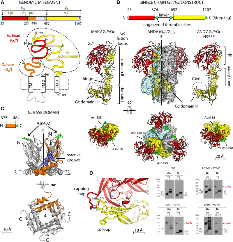
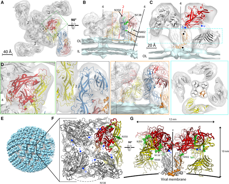
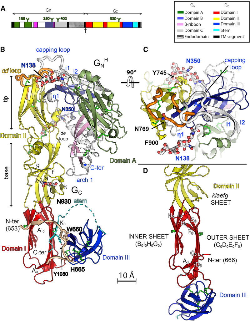
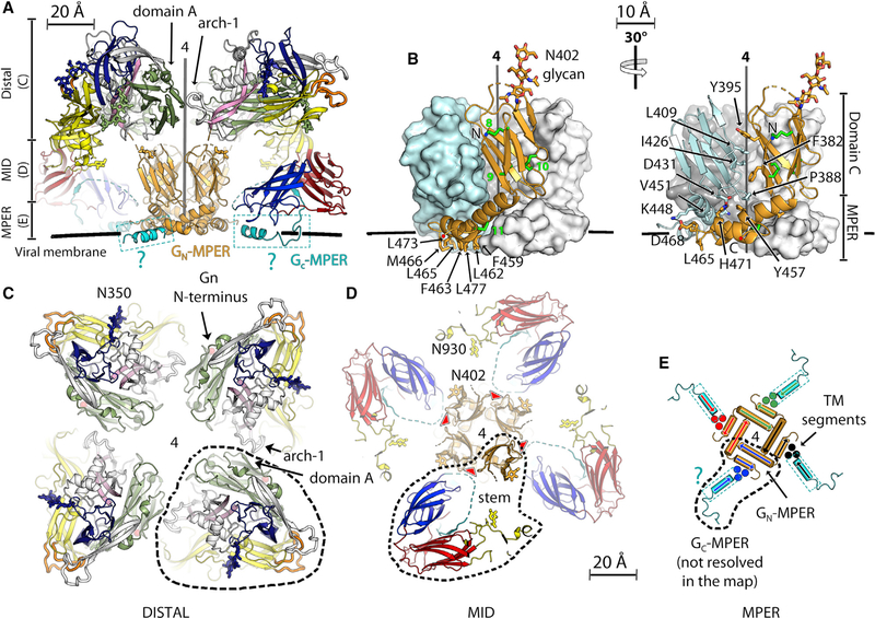
Hantaviruses are rodent-borne viruses causing serious zoonotic outbreaks worldwide for which no treatment is available. Hantavirus particles are pleomorphic and display a characteristic square surface lattice. The envelope glycoproteins Gn and Gc form heterodimers that further assemble into tetrameric spikes, the lattice building blocks. The glycoproteins, which are the sole targets of neutralizing antibodies, drive virus entry via receptor-mediated endocytosis and endosomal membrane fusion. Here we describe the high-resolution X-ray structures of the heterodimer of Gc and the Gn head and of the homotetrameric Gn base. Docking them into an 11.4-Å-resolution cryoelectron tomography map of the hantavirus surface accounted for the complete extramembrane portion of the viral glycoprotein shell and allowed a detailed description of the surface organization of these pleomorphic virions. Our results, which further revealed a built-in mechanism controlling Gc membrane insertion for fusion, pave the way for immunogen design to protect against pathogenic hantaviruses.

Keywords: bunyaviruses; class-II fusion protein; hantavirus pulmonary sydnrome; hantaviruses; membrane fusion; viral surface glycoprotein layer; virus assembly; virus entry; virus structure.


Conflict of interest statement

Declaration of Interests E.A.B., N.D.T., F.A.R., and P.G.-C. are coinventors of a pending patent application for development of stabilized immunogens for an Andes virus vaccine. K.C. is a member of the scientific advisory board of Integrum Scientific, LLC. F.A.R. is on the board of Virtexx, SAS.

Figures

Figure 1.
Figure 1.. X-Ray Structures of the Hantavirus Glycoproteins
(A) Domain organization of the hantavirus M segment. The top panel shows a linear diagram colored according to protein domains, with the signalase cleavage site (Gc N terminus) marked by an arrow. Glycosylated asparagines are labeled in green above the open reading frame (ORF). The bottom panel shows a schematic of the Gn/Gc heterodimer, with the viral membrane as a dashed box and TM segments indicated. The ectodomains of Gn and Gc are colored, with N-linked glycans indicated by “Y” symbols. Dashed ovals outline the two separate fragments whose structures were determined here. (B) Structures of the hantavirus GnH/Gc heterodimer. First row: diagram of the single-chain GnH/Gc construct used for crystallization upon thrombin treatment (engineered thrombin sites are shown in green). The second and third rows show two orthogonal views of MAPV GnH/Gc (left), ANDV (GnH/Gc)3; center), and the ANDV GnH/Gc-H953F mutant (right). In the center panel, the (GnH/Gc)3 trimer is shown with Gc in yellow, gray, and light cyan surfaces and Gn as red ribbons. In the side view (second row), the front Gn chain was omitted for clarity, and the matching Gc chain is shown as yellow ribbons as in the left and right panels. All three panels in this row display Gc domain I in the same orientation. The top view (third row) also shows the glycan chains as green sticks and labeled. (C) Structure of the ANDV GnB tetramer in side view (top) and bottom view (bottom panel), with one GnB chain highlighted in orange. The glycan attached to N402 in GnB is indicated as green sticks. The density corresponding to an omit map contoured at 1.5 σ is shown in blue, marking a reacting groove that binds a ligand from the supernatant (STAR Methods). We postulate that, in the spike, the Gc stem may run within this groove. (D) Engineering of inter-chain disulfide bonds. Left panel: close up of the GnH/Gc interface marking the location of pairs of residues mutated to cysteine (connected by green bars and labeled).The right panel shows an SDS-PAGE analysis of VLPs released into the supernatant of cells expressing wild-type ANDV Gn/Gc and the indicated Cys double mutants under reducing and non-reducing conditions (as indicated).
Figure 2.
Figure 2.. Organization of Hantavirus Gn/Gc Spikes on Virions
(A) The 11.4-Å-resolution cET-STA map of the Tula virus spike plus the asymmetric unit of its four neighbor spikes viewed from the top, along the 4-fold axis and with the docked X-ray structures of the ANDV GnH/Gc-H953F mutant. One protomer of the spike is colored as in Figure 1. A protomer of the adjacent spike, related by a local 2-fold axis, is highlighted in salmon and blue for GnH and Gc, respectively. (B) Orthogonal view of the spike with the 4-fold axis in the plane of the figure. The conserved N-linked glycan chains are shown as green sticks and labeled. OL and IL indicate the outer and inner leaflets of the viral membrane, respectively. (C) Close up of the spike showing the GnB tetramer (for clarity, the Gc moiety in the front was removed). The N and C termini of GnH and GnB are indicated and labeled in blue and black, respectively. (D) Close ups of selected regions corresponding to the dashed boxes in (A)–(C) to show the quality of the fit, color-framed to match the corresponding boxed areas (dashed lines) in the panels just above (see also Video S1). (E) Reconstruction of a Tula virus particle generated by back-projecting the 11.4-Å cET/STA density of the spike to the original spike locations on a particle. The resulting surface protein lattice is shown in cyan and the viral membrane in gray. (F and G) The spike in a top view (F), with one of the four protomers colored as in Figure 1 and the sugar residues in green, and in side view (G). As in (C), the Gc subunit at the forefront (marked by a dashed oval in F) was omitted in (G) to visualize the GnB tetramer at the spike center. The GnH N and C termini are marked as in (C) (only the N-termini in G for clarity).
Figure 3.
Figure 3.. The Hantavirus Gn/Gc Pre-fusion Heterodimer
(A) The single ORF of the hantavirus genomic RNA segment M colored by domains according to the key on the right. N-glycosylation sites are shown as “Y” symbols (ANDV numbering; Figure S1). (B) The 2.2-Å-resolution X-ray structure of the MAPV GnH/Gc heterodimer colored as in (A), with the disulfide bonds shown in green and the N-glycans displayed as sticks colored according to atom type. (C) Orthogonal view of the GnH/Gc interface seen from the domain II tip. (D) Ribbon representation of HNTV Gc monomer (PDB: 5LJY) centered on domain I, showing the extended conformation adopted by Gc in the absence of the stem. Domain I is in the same orientation in (B) and (D). The Gc N-tail in the left panel is highlighted in light brown and displayed as thicker tubes, and the stem is shown in cyan.
Figure 4.
Figure 4.. Inter-chain Contacts Stabilizing the Hantavirus Spike
(A) Side view of the spike, omitting the front Gc subunit for clarity. The four protomers are colored as in Figure 3, with GnB shown in orange. The Gc-MPER, not resolved in the structure, was modeled as an α helix (colored cyan) to indicate its putative location in the lipid head region of the membrane’s outer layer (indicated schematically by a thick black line). (B) X-ray structure of GnB. Disulfide bonds are indicated in the front protomer as green sticks and numbered. The side chains of non-polar residues of the MPER exposed to the viral membrane are shown as sticks and labeled on the left, whereas the right panel shows the interactions between two protomers with interfacial residues highlighted. (C–E) Slices of the spike model normal to the 4-fold axis, corresponding to the regions indicated in the vertical bar at the left of (A). A dashed outline follows the contour of one spike protomer along the three radial sections displayed. (C) Contacts in the membrane-distal region (the spike’s “crown”). The Asn350 glycan is shown as blue sticks. (D) The spike’s “midregion,” displaying two glycans attached to Asn402 and Asn930 that fill the internal cavities under the spike crown. The segment of the Gc stem that is disordered in the X-ray structure (dotted line in Figure 3B) projects into a cET density volume in close proximity with the reactive groove (red arrowheads) at the GnB tetramer interface (indicated in blue in Figure 1C). (E) The membrane-proximal region. The two amphipathic helices of the Gn MPER (at the GnB C terminus) and the predicted Gc MPER, which precede the TM segments, form a supporting platform embedded in the OL of the viral membrane. The approximate locations of the three TM segments per protomer are indicated by full blue circles. The directionality of the helices is indicated by arrows. A thin dashed rectangle surrounding theGc MPER helix and the cyan question mark were added to indicate that this segment was not resolved in the X-ray structure.
Figure 5.
Figure 5.. Conformational Change of the Gc Domain II Tip for TMIS Formation
(A) The post-fusion conformation. The left and central panels show a top view (along the 3-fold axis) and a side view of the ANDV (Gn/Gc)3 trimer, with Gc in the characteristic post-fusion hairpin conformation displayed in surface representation and Gn shown as green ribbons. One Gc subunit is colored by domains, with Tyr739, Trp766, and Phe900 of the TMIS displayed and labeled. For clarity, the Gn polypeptide chain in the front was omitted in the side view. N-linked glycans are shown as thick sticks. The right panel shows the structure of the ANDV Gc post-fusion trimer crystallized at pH 7.5 and depicted as in the central panel. The horizontal bar indicates the target membrane into which the TMIS would insert. (B) The tip of MAPV Gc domain II showing the organization of the bc, cd, and ij loops in the pre-fusion (top) and post-fusion (bottom) conformations, from the 2.2- and 2.4-Å resolution structures, respectively (Table 1). The left and right panels show two orthogonal views, as indicated. Side chains important for target membrane insertion and forming the polar network around Glu757-Asp759 are highlighted. In the pre-fusion conformation, the bc and ij loops are buried by the Gn N138 glycan and the capping loop, respectively, as indicated.

References

    1. Acuña R, Bignon EA, Mancini R, Lozach PY, and Tischler ND (2015). Acidification triggers Andes hantavirus membrane fusion and rearrangement of Gc into a stable post-fusion homotrimer. J. Gen. Virol. 96, 3192–3197. - PubMed
    1. Antic D, Wright KE, and Kang CY (1992). Maturation of Hantaan virus glycoproteins G1 and G2. Virology 189, 324–328. - PubMed
    1. Ashkenazy H, Abadi S, Martz E, Chay O, Mayrose I, Pupko T, and Ben- Tal N (2016). ConSurf 2016: an improved methodology to estimate and visualize evolutionary conservation in macromolecules. Nucleic Acids Res. 44 (W1), W344–50. - PMC - PubMed
    1. Battisti AJ, Chu YK, Chipman PR, Kaufmann B, Jonsson CB, and Rossmann MG (2011). Structural studies of Hantaan virus. J. Virol. 85, 835–841. - PMC - PubMed
    1. Bharat TA, and Scheres SH (2016). Resolving macromolecular structures from electron cryo-tomography data using subtomogram averaging in RELION. Nat. Protoc. 11, 2054–2065. - PMC - PubMed

Publication types

MeSH terms

LinkOut - more resources