

Full-Azimuth Beam Steering MIMO Antenna Arranged in a Daisy Chain Array Structure
- PMID: 32961809
- PMCID: PMC7569998
- DOI: 10.3390/mi11090871
Full-Azimuth Beam Steering MIMO Antenna Arranged in a Daisy Chain Array Structure
Abstract
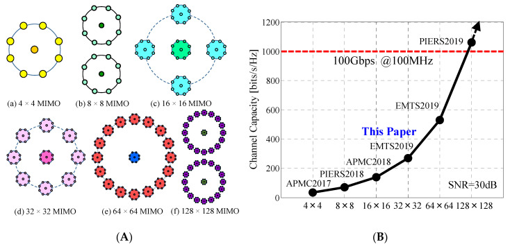
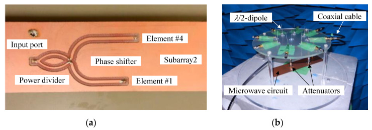
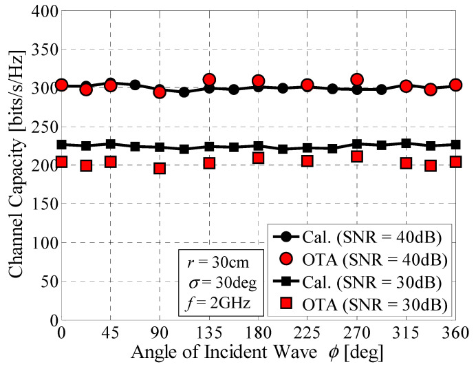
This paper presents a multiple-input, multiple-output (MIMO) antenna system with the ability to perform full-azimuth beam steering, and with the aim of realizing greater than 20 Gbps vehicular communications. The MIMO antenna described in this paper comprises 64 elements arranged in a daisy chain array structure, where 32 subarrays are formed by pairing elements in each subarray; the antenna yields 32 independent subchannels for MIMO transmission, and covers all communication targets regardless of their position relative to the array. Analytical results reveal that the proposed antenna system can provide a channel capacity of more than 200 bits/s/Hz at a signal-to-noise power ratio (SNR) of 30 dB over the whole azimuth, which is equivalent to 20 Gbps for a bandwidth of 100 MHz. This remarkably high channel capacity is shown to be due to two significant factors; the improved directivity created by the optimum in-phase excitation and the low correlation between the subarrays due to the orthogonal alignment of the array with respect to the incident waves. Over-the-air (OTA) experiments confirm the increase in channel capacity; the proposed antenna can maintain a constant transmission rate over all azimuth angles.
Keywords: Monte Carlo simulation; beam steering array; connected car; daisy chain multiple-input multiple-output (MIMO) antenna; large-scale MIMO; over-the-air (OTA) testing.
Conflict of interest statement
The authors declare no conflict of interest.
Figures


References
-
- Rusek F., Persson D., Lau B.K., Larsson E.G., Marzetta T.L., Edfors O., Tufvesson F. Scaling Up MIMO: Opportunities and challenges with very large MIMO. IEEE Signal. Process. Mag. 2012;30:40–60. doi: 10.1109/MSP.2011.2178495. - DOI
-
- Larsson E.G., Edfors O., Tufvesson F., Marzetta T.L. Massive MIMO for Next Generation Wireless Systems. IEEE Commun. Mag. 2014;52:186–195. doi: 10.1109/MCOM.2014.6736761. - DOI
-
- Kibaroglu K., Sayginer M., Phelps T., Rebeiz G.M. A 64-Element 28-GHz Phased-Array Transceiver With 52-dBm EIRP and 8–12-Gb/s 5G Link at 300 Meters without Any Calibration. IEEE Trans. Microw. Theory Technol. 2018;66:5796–5811. doi: 10.1109/TMTT.2018.2854174. - DOI
-
- Yamaguchi S., Nakamizo H., Shinjo S., Tsutsumi K., Fukasawa T., Miyashita H. Development of active phased array antenna for high SHF wideband massive MIMO in 5G; Proceedings of the 2017 IEEE International Symposium on Antennas and Propagation & USNC/URSI National Radio Science Meeting; San Diego, CA, USA. 9–14 July 2017; pp. 1463–1464.
-
- Mao C.-X., Gao S., Wang Y. Broadband High-Gain Beam-Scanning Antenna Array for Millimeter-Wave Applications. IEEE Trans. Antennas Propag. 2017;65:4864–4868. doi: 10.1109/TAP.2017.2724640. - DOI
Grants and funding
LinkOut - more resources
Full Text Sources
Miscellaneous
