. 2020 Sep 22;7(5):054303.
doi: 10.1063/4.0000020. eCollection 2020 Sep.

Repetitive non-thermal melting as a timing monitor for femtosecond pump/probe X-ray experiments

Affiliations

Repetitive non-thermal melting as a timing monitor for femtosecond pump/probe X-ray experiments

Å U J Bengtsson et al. Struct Dyn. .

Abstract

Time-resolved optical pump/X-ray probe experiments are often used to study structural dynamics. To ensure high temporal resolution, it is necessary to monitor the timing between the X-ray pulses and the laser pulses. The transition from a crystalline solid material to a disordered state in a non-thermal melting process can be used as a reliable timing monitor. We have performed a study of the non-thermal melting of InSb in single-shot mode, where we varied the sample temperature in order to determine the conditions required for repetitive melting. We show how experimental conditions affect the feasibility of such a timing tool.


Figures

FIG. 1.
FIG. 1.
Experimental setup. The difference in the incidence angle between the pump and probe beam will map the spatial extent of the sample into a time axis.
FIG. 2.
FIG. 2.
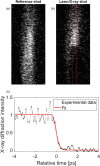
(a) and (b) show the reference shot and the shot with the laser, respectively. Time increases from the top of the images to the bottom. The red dashed lines in the laser shot indicate the part of the image used in the analysis, where the laser has a uniform fluence. (c) shows the laser shot (normalized using the reference shot) together with a Gaussian fit. Time zero is defined as the time at which the intensity has decreased to 50%. This dataset was acquired at 300 K.
FIG. 3.
FIG. 3.
X-ray diffraction intensity of reference shots as a function of the number of shots at the different temperatures investigated. The intensity is normalized to the intensity of the first shot at each temperature.
FIG. 4.
FIG. 4.
Images of (a) the reference shot, (b) the first laser/X-ray shot on the pristine sample, and (c) the twentieth laser/X-ray shot on the same position. The green dashed rectangle indicates the increase in the X-ray diffraction intensity seen in the later shots. The data were acquired at 500 K.
FIG. 5.
FIG. 5.
Edge contrast between the X-ray intensity before and after time zero for 130 mJ/cm2 and 90 mJ/cm2, respectively.
FIG. 6.
FIG. 6.
FemtoMAX timing tool reading as a function of time zero determined from non-thermal melting. The data points are color-coded according to the number of shots; the first shot is being shown in purple and the last shot in yellow. The black line is a linear fit, and the standard deviation of 600 fs is the intrinsic jitter of the RF-cavity-based jitter monitor.
FIG. 7.
FIG. 7.
The left and right parts of the image were split into two separate channels, which were evaluated separately. This mimics the use of two identical set-ups to evaluate the performance of the timing monitor for 100 shots.
FIG. 8.
FIG. 8.
Schematic image of the InSb timing monitor setup.

References

    1. Lindenberg A. M., Johnson S. L., and Reis D. A., “ Visualization of atomic-scale motions in materials via femtosecond x-ray scattering techniques,” Annu. Rev. Mater. Res. 47, 425–449 (2017).10.1146/annurev-matsci-070616-124152 - DOI
    1. Buzzi M. et al., “ Probing dynamics in quantum materials with femtosecond x-rays,” Nat. Rev. Mater. 3(9), 299–311 (2018).10.1038/s41578-018-0024-9 - DOI
    1. Moeller S. et al., “ Photon beamlines and diagnostics at LCLS,” Nucl. Instrum. Methods Phys. Res. Sect. A 635, S6–S11 (2011).10.1016/j.nima.2010.10.125 - DOI
    1. Yabashi M., Tanaka H., and Ishikawa T., “ Overview of the SACLA facility,” J. Synchrotron Radiat. 22, 477–484 (2015).10.1107/S1600577515004658 - DOI - PMC - PubMed
    1. Milne C. J. et al., “ SwissFEL: The Swiss x-ray free electron laser,” Appl. Sci. 7(7), 720 (2017).10.3390/app7070720 - DOI