

Novel Method for the Manufacture of Complex CFRP Parts Using FDM-based Molds
- PMID: 32992631
- PMCID: PMC7600514
- DOI: 10.3390/polym12102220
Novel Method for the Manufacture of Complex CFRP Parts Using FDM-based Molds
Abstract
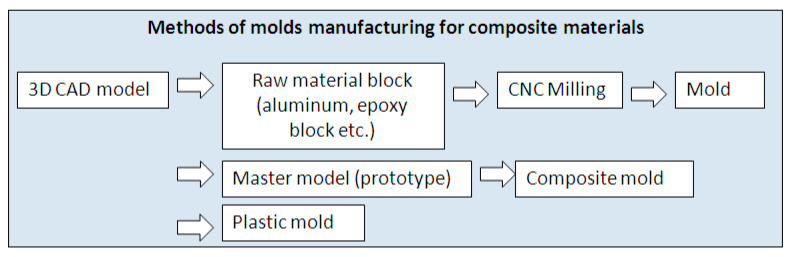
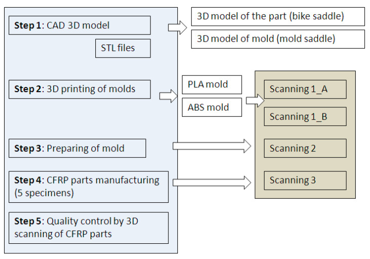
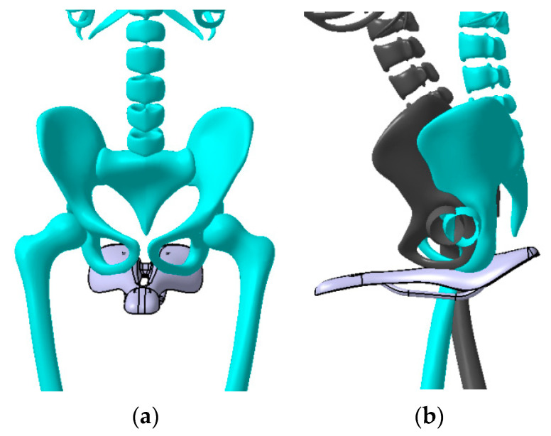
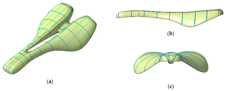
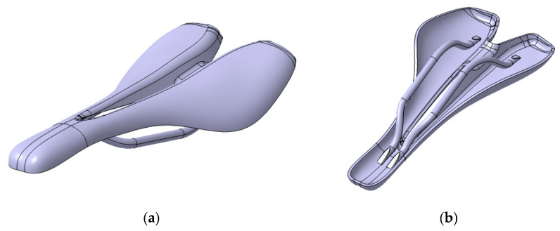
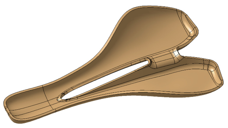
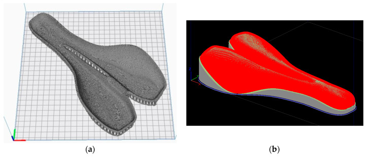
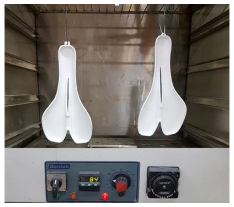
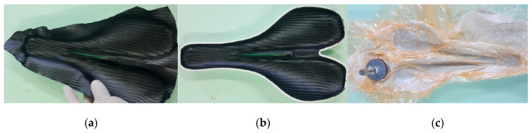
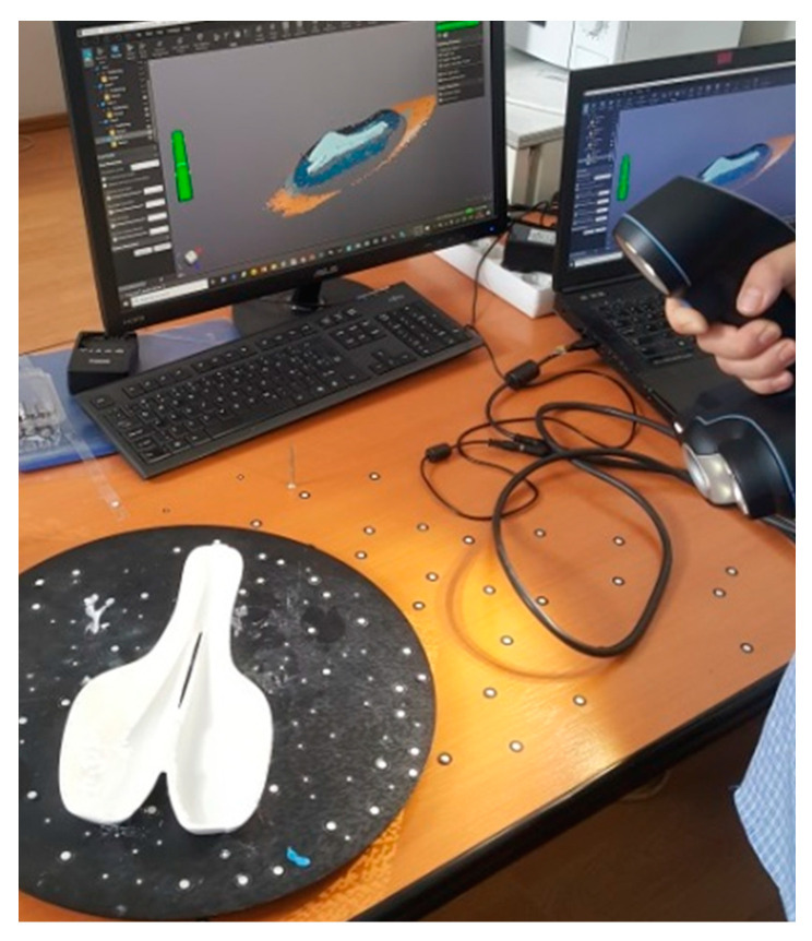
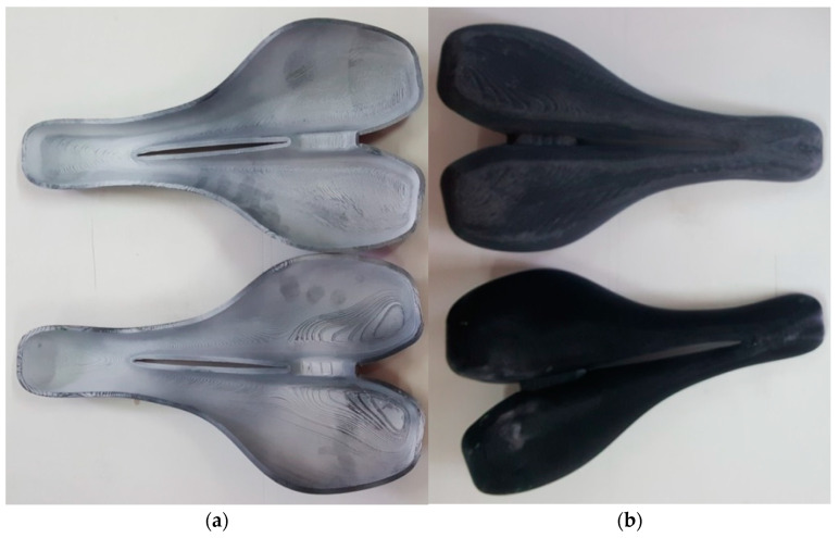
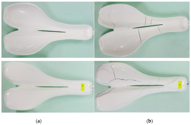
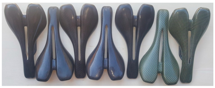
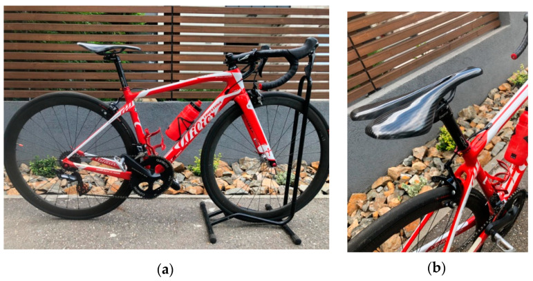
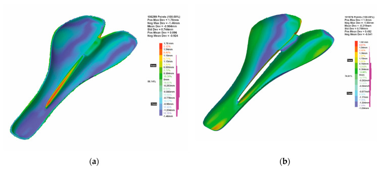
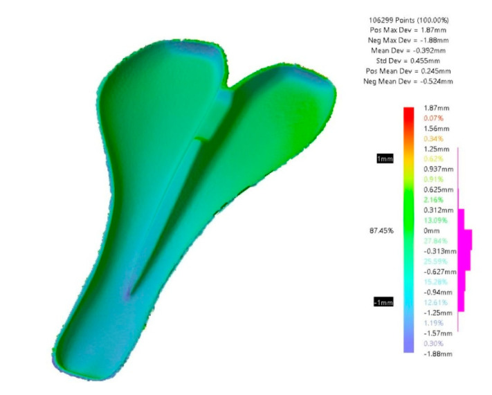
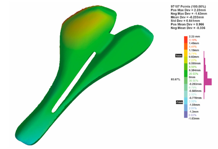
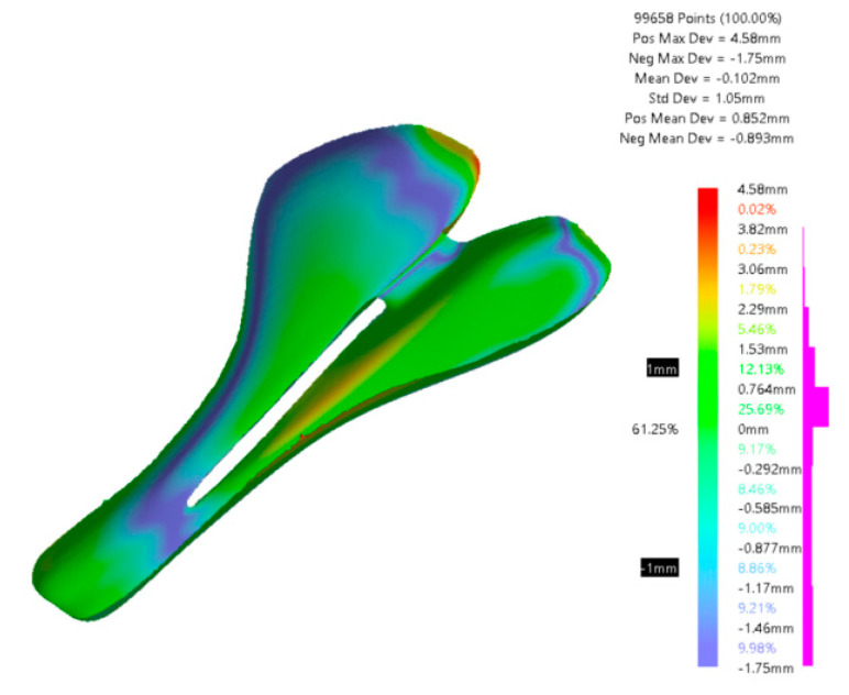
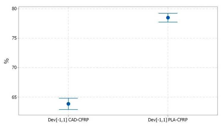
Fibre-reinforced polymers (FRP) have attracted much interest within many industrial fields where the use of 3D printed molds can provide significant cost and time savings in the production of composite tooling. Within this paper, a novel method for the manufacture of complex-shaped FRP parts has been proposed. This paper features a new design of bike saddle, which was manufactured through the use of molds created by fused deposition modeling (FDM), of which two 3D printable materials were selected, polylactic acid (PLA) and acrylonitrile butadiene styrene (ABS), and these molds were then chemically and thermally treated. The novel bike saddles were fabricated using carbon fiber-reinforced polymer (CFRP), by vacuum bag technology and oven curing, utilizing additive manufactured (AM) molds. Following manufacture the molded parts were subjected to a quality inspection, using non-contact three-dimensional (3D) scanning techniques, where the results were then statistically analyzed. The statistically analyzed results state that the main deviations between the CAD model and the manufactured CFRP parts were within the range of ±1 mm. Additionally, the weight of the upper part of the saddles was found to be 42 grams. The novel method is primarily intended to be used for customized products using CFRPs.
Keywords: 3D scanning; CFRP; PLA mold; additive manufacturing; bike saddle; fused deposition modeling; vacuum bag technology.
Conflict of interest statement
The authors declare no conflict of interest.
Figures
References
-
- Henderson L. Carbon Fibers and Their Composite Materials. MDPI AG; Basel, Switzerland: 2019. ISBN-13: 978-3039211029, ISBN-10: 3039211021.
-
- Barbero E.J. Introduction to Composite Materials Design. 3rd ed. CRC Press; Boca Raton, FL, USA: 2018.
-
- Tofail S.A.M., Koumoulos E.P., Bandyopadhyay A., Bose S., O’Donoghue L., Charitidis C. Additive manufacturing: Scientific and technological challenges, market uptake and opportunities. Mater. Today. 2018;21:22–37. doi: 10.1016/j.mattod.2017.07.001. - DOI
-
- International Organization for Standardization . Standard Terminology for Additive Manufacturing–General Principles–Terminology. ISO/ASME International; Geneva, Switzerland: 2015. (ISO/ASTM 52900-15).
-
- Turner B.N., Strong R., Gold S.A. A review of melt extrusion additive manufacturing processes: I. Process design and modeling. Rapid Prototyp. J. 2014;20:192–204. doi: 10.1108/RPJ-01-2013-0012. - DOI
Grants and funding
LinkOut - more resources
Full Text Sources
Miscellaneous
