. 2020 Sep 29;10(1):15951.
doi: 10.1038/s41598-020-72603-5.

Camera-based optical palpation

Affiliations

Camera-based optical palpation

Rowan W Sanderson et al. Sci Rep. .

Abstract

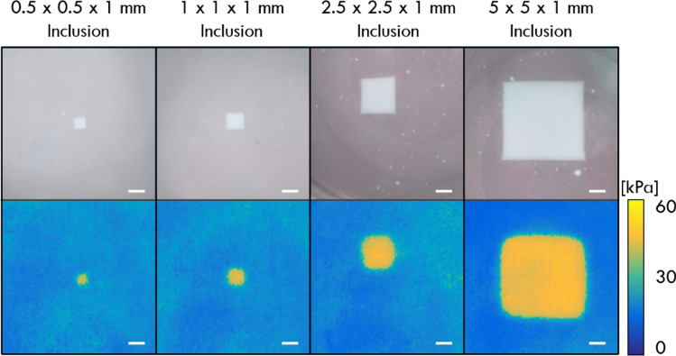
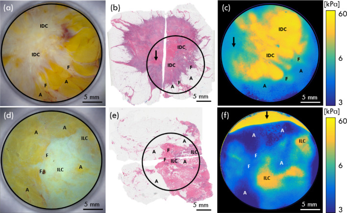
Optical elastography is undergoing extensive development as an imaging tool to map mechanical contrast in tissue. Here, we present a new platform for optical elastography by generating sub-millimetre-scale mechanical contrast from a simple digital camera. This cost-effective, compact and easy-to-implement approach opens the possibility to greatly expand applications of optical elastography both within and beyond the field of medical imaging. Camera-based optical palpation (CBOP) utilises a digital camera to acquire photographs that quantify the light intensity transmitted through a silicone layer comprising a dense distribution of micro-pores (diameter, 30-100 µm). As the transmission of light through the micro-pores increases with compression, we deduce strain in the layer directly from intensity in the digital photograph. By pre-characterising the relationship between stress and strain of the layer, the measured strain map can be converted to an optical palpogram, a map of stress that visualises mechanical contrast in the sample. We demonstrate a spatial resolution as high as 290 µm in CBOP, comparable to that achieved using an optical coherence tomography-based implementation of optical palpation. In this paper, we describe the fabrication of the micro-porous layer and present experimental results from structured phantoms containing stiff inclusions as small as 0.5 × 0.5 × 1 mm. In each case, we demonstrate high contrast between the inclusion and the base material and validate both the contrast and spatial resolution achieved using finite element modelling. By performing CBOP on freshly excised human breast tissue, we demonstrate the capability to delineate tumour from surrounding benign tissue.


Conflict of interest statement

B.F.K., C.M.S., A.C. and B.L. hold shares in OncoRes Medical, a startup company developing optical coherence elastography for surgical applications. B.F.K. and A.C. receive research funding from this company. The other authors declare no conflicts of interest related to this article.

Figures

Figure 1
Figure 1
Fabrication process of micro-porous silicone layers by sacrificial templating of sugar grains.
Figure 2
Figure 2
Working principle of CBOP. A CMOS camera is used to measure the transmission of light emitted by LEDs through the micro-porous layer and reflected back from the green layer under (a) low preloaded strain, (b) moderate preloaded strain and (c) high preloaded strain; C camera, L LEDs, W glass window, PL micro-porous layer, GL green layer, S sample. The insets from the camera show the change in green intensity with different preloaded strains. The micro-porous layer inset illustrates the reduction in pore size under increasing compression.
Figure 3
Figure 3
Layer characterisation and generation of optical palpograms. (a) The saturation-strain characterisation curve, (b) the stress–strain characterisation curve of the micro-porous silicone layer and (c) the resulting stress-saturation curve. (d) Digital photograph of micro-porous layer of phantom containing a 2.5 × 2.5 mm inclusion phantom at 50% preloaded strain, and (e) the corresponding colour saturation image where the red and blue circles represent the relative colour saturation through a region of the inclusion and base, respectively. (f) The optical palpogram is produced by equating each pixel in (e) to a stress value using the stress–strain curve in (c).
Figure 4
Figure 4
Photographs and optical palpograms acquired at 50% preloaded strain for four different-sized inclusion phantoms. Photographs are provided for validation purposes only to show the relative positions of the inclusions and were taken without the micro-porous layer. Scale bars: 1 mm.
Figure 5
Figure 5
Analysis of the lateral resolutions of CBOP and OCT-based optical palpation. Optical palpograms acquired using (a) CBOP at 50% bulk preloaded strain, (b) FEM of CBOP and (c) OCT-based optical palpation at 50% bulk preloaded strain on a 2.5 × 2.5 × 1 mm inclusion embedded within a soft phantom. The normalised step response (coloured points) and error function (black line) of (d) CBOP, (e) FEM and (f) OCT-based optical palpation are taken across the boundary of the same inclusion phantom. (g) The lateral resolution measured using CBOP, OCT-based optical palpation and FEA, across five locations on each inclusion phantom with error bars representing one standard deviation.
Figure 6
Figure 6
CBOP performed on two freshly excised mastectomy specimens containing (ac) IDC and (df) ILC. (a) Photograph, (b) histology and (c) optical palpogram at 30% preloaded strain. (d) Photograph (e) histology image and (f) optical palpogram at 60% preloaded strain. The images have been annotated to show regions of invasive ductal carcinoma (IDC), invasive lobular carcinoma (ILC), fibrous tissue (F) and adipose tissue (A) and black circles on the histology images mark the approximate region where CBOP was taken relative to the whole specimen. The arrows in (b,c,f) indicate regions of imaging artefacts. Optical palpograms have been displayed on a logarithmic scale to enhance mechanical contrast between tissue types.

References

    1. Kennedy BF, Wijesinghe P, Sampson DD. The emergence of optical elastography in biomedicine. Nat. Photonics. 2017;11:215. doi: 10.1038/nphoton.2017.6. - DOI
    1. Wang S, Larin KV. Optical coherence elastography for tissue characterization: A review. J. Biophotonics. 2015;8:279–302. doi: 10.1002/jbio.201400108. - DOI - PMC - PubMed
    1. Kennedy BF, Kennedy KM, Sampson DD. A review of optical coherence elastography: Fundamentals, techniques and prospects. IEEE J. Sel. Top. Quant. 2014;20:272–288. doi: 10.1109/JSTQE.2013.2291445. - DOI
    1. Liang X, Crecea V, Boppart SA. Dynamic optical coherence elastography: A review. J. Innov. Opt. Heal. Sci. 2010;03:221–233. doi: 10.1142/S1793545810001180. - DOI - PMC - PubMed
    1. Zaitsev, V. Y. et al. Strain and elasticity imaging in compression optical coherence elastography: the two-decade perspective and recent advances. J. Biophotonicsn/a, e202000257. - PubMed

Publication types