. 2020 Oct 2;11(1):4975.
doi: 10.1038/s41467-020-18775-0.

A defect-resistant Co-Ni superalloy for 3D printing

Affiliations

A defect-resistant Co-Ni superalloy for 3D printing

Sean P Murray et al. Nat Commun. .

Abstract

Additive manufacturing promises a major transformation of the production of high economic value metallic materials, enabling innovative, geometrically complex designs with minimal material waste. The overarching challenge is to design alloys that are compatible with the unique additive processing conditions while maintaining material properties sufficient for the challenging environments encountered in energy, space, and nuclear applications. Here we describe a class of high strength, defect-resistant 3D printable superalloys containing approximately equal parts of Co and Ni along with Al, Cr, Ta and W that possess strengths in excess of 1.1 GPa in as-printed and post-processed forms and tensile ductilities of greater than 13% at room temperature. These alloys are amenable to crack-free 3D printing via electron beam melting (EBM) with preheat as well as selective laser melting (SLM) with limited preheat. Alloy design principles are described along with the structure and properties of EBM and SLM CoNi-base materials.


Conflict of interest statement

UCSB has a pending patent (T.M.P. and S.P.M. as inventors) on SB–CoNi alloys: "High Temperature Oxidation Resistant Co-based Gamma/Gamma Prime Alloys DMREF-Co", US patent application number US16/375,687, publication number US20200140978A1, international patent application number PCT/US2019/025882, international publication number WO2019195612A1. All other authors declare no competing interests.

Figures

Fig. 1
Fig. 1. Additive manufacturing of a CoNi-base superalloy through EBM and SLM.
SEM micrographs of metal powder of SB-CoNi-10 used for a EBM and b SLM printing trials. Simple bar geometries have been printed for uniaxial tensile testing c, d in addition to complex geometries such as prototype turbine blades with e internal cooling channels or f thin, over-hanging platforms. IPF maps acquired through EBSD show the grain structure of the as-printed CoNi-base superalloy along the build direction manufactured through g EBM and h SLM. The scale bars for a, b and g, h are 500 μm. The scale bars for cf are 2 cm.
Fig. 2
Fig. 2. As-printed chemical segregation after Bridgman casting, EBM, and SLM.
BSE micrographs of the XY-plane microstructures of SB-CoNi-10 after fabrication through a Bridgman casting, b EBM, and c SLM. Quantitative compositional data and Scheil curve fits for the apparent distribution coefficients are shown for the d Bridgman, e EBM, and f SLM samples. EPMA grid scans of 20 × 20 evenly spaced points were collected in the centers of the BSE images shown in ac with grid dimensions of a 1 × 1 mm and b, c 100 × 100 μm. Scale bars for a, b, and c are 500, 50, and 50 μm, respectively.
Fig. 3
Fig. 3. Quantitative EPMA maps.
EPMA elemental composition maps of the XY-plane microstructures for the a EBM and b SLM samples. Co, Cr, and W segregate to the dendrite core while Ni, Al, and Ta segregate to the interdendritic regions. Each map has a step size of 0.5 μm. The scale bars for a and b are 100 μm.
Fig. 4
Fig. 4. EBM microstructural evolution before and after post-processing.
a Stitched BSE image of the final build layers in as-printed EBM SB-CoNi-10. BSE micrographs of the as-printed EBM alloy at different depths below the final build layer: b near the final build layer, c 1 mm below, d 2 mm below, and e 4 mm below. f IPF map of the as-printed EBM alloy and g IPF map of the HIP + SHT + aged material. Both EBSD scans were acquired at a similar distance from the final build layer (~22 mm) that is representative of the center of the tensile specimen gauge sections. h, i Additional BSE micrographs of the γγ microstructure after post-processing. The scale bar for a is 500 μm. The scale bars for be are 5 μm. The scale bars for f and g are 500 μm. The scale bar for h is 25 μm. The scale bar for i is 5 μm.
Fig. 5
Fig. 5. SLM microstructural evolution before and after post-processing.
a Stitched BSE image of the as-printed SLM microstructure of SB-CoNi-10 with characteristic melt pool boundaries visible. BSE micrographs of the as-printed EBM alloy at different depths below the final build layer: b near the final build layer, c 1 mm below, d 2 mm below, and e 4 mm below. f IPF map of the as-printed SLM alloy and g IPF map of the HIP + SHT + aged material. h, i Additional BSE micrographs of the γγ microstructure after post-processing. The bright particles are Ta-rich carbides which are a result of the addition of carbon. The scale bar for a is 50 μm. The scale bars for be are 5 μm. The scale bars for f and g are 500 μm. The scale bar for h is 25 μm. The scale bar for i is 5 μm.
Fig. 6
Fig. 6. Tensile testing of EBM and SLM SB-CoNi-10 at room temperature.
Stress–strain curves for quasi-static tensile tests at room temperature on the a EBM and f SLM materials in the as-printed and HIP + SHT + aged conditions compared to EBM CM 247 and SLM IN738LC. SEM fractography of the be EBM samples and the gj SLM samples in the b, c, g, h as-printed and d, e, i, j HIP + SHT + aged conditions reveal features indicative of ductile fracture in all specimens. The higher magnification images are taken near the center of each fracture surface. The scale bars for b, d are 1 mm. The scale bars for g, i are 2 mm. The scale bars for c, e, h, j are 5 μm.
Fig. 7
Fig. 7. EBSD of post-mortem EBM tensile specimens.
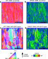
a, c IPF maps and b, d grain reference orientation deviation (GROD) maps show the accumulation of plastic strain after tensile testing of the EBM material in the a, b as-printed and c, d HIP + SHT + aged conditions. The scale bars are 500 μm.

References

    1. Pollock TM. Alloy design for aircraft engines. Nat. Mater. 2016;15:809–815. doi: 10.1038/nmat4709. - DOI - PubMed
    1. Roca JB, Vaishnav P, Fuchs ERH, Morgan MG. Policy needed for additive manufacturing. Nat. Mater. 2016;15:815–818. doi: 10.1038/nmat4658. - DOI - PubMed
    1. DebRoy T, et al. Scientific, technological and economic issues in metal printing and their solutions. Nat. Mater. 2019;18:1026–1032. doi: 10.1038/s41563-019-0408-2. - DOI - PubMed
    1. Heinl P, et al. Cellular Ti–6Al–4V structures with interconnected macro porosity for bone implants fabricated by selective electron beam melting. Acta Biomater. 2008;4:1536–1544. doi: 10.1016/j.actbio.2008.03.013. - DOI - PubMed
    1. Yap CY, et al. Review of selective laser melting: materials and applications. Appl. Phys. Rev. 2015;2:041101. doi: 10.1063/1.4935926. - DOI