Review
. 2020 Oct;10(10):2006-2029.
doi: 10.21037/qims-19-1036.

The clinical utilities of multi-pinhole single photon emission computed tomography

Affiliations
Review

The clinical utilities of multi-pinhole single photon emission computed tomography

Ilker Ozsahin et al. Quant Imaging Med Surg. 2020 Oct.

Abstract

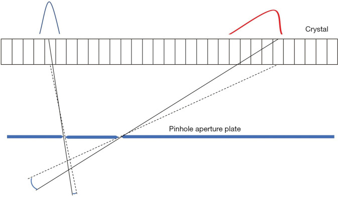
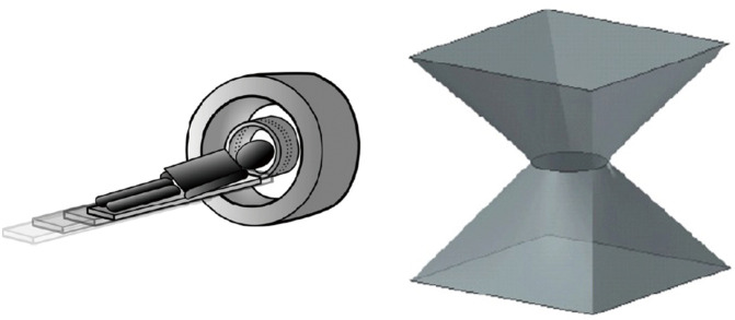
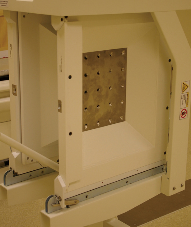
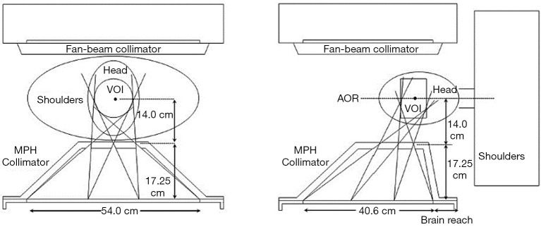
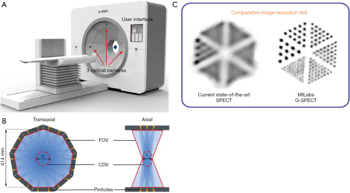
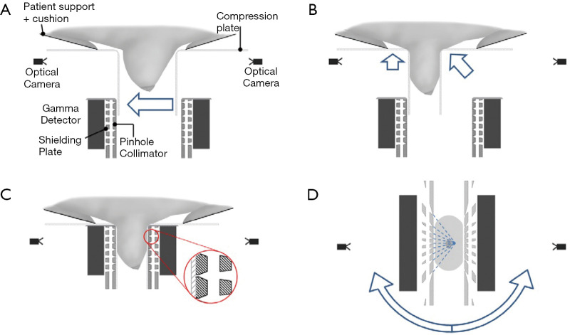
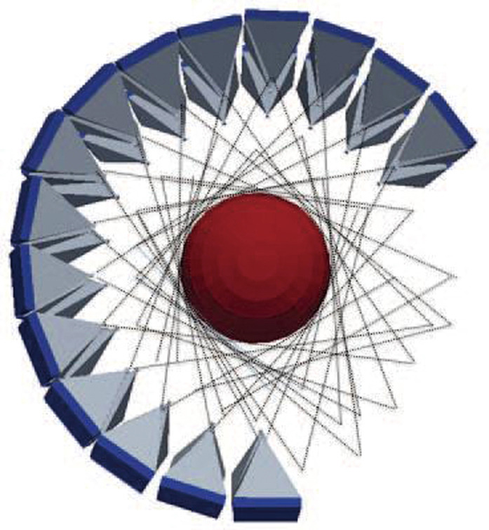
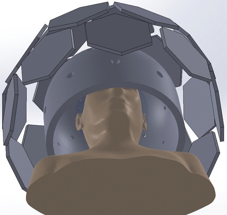
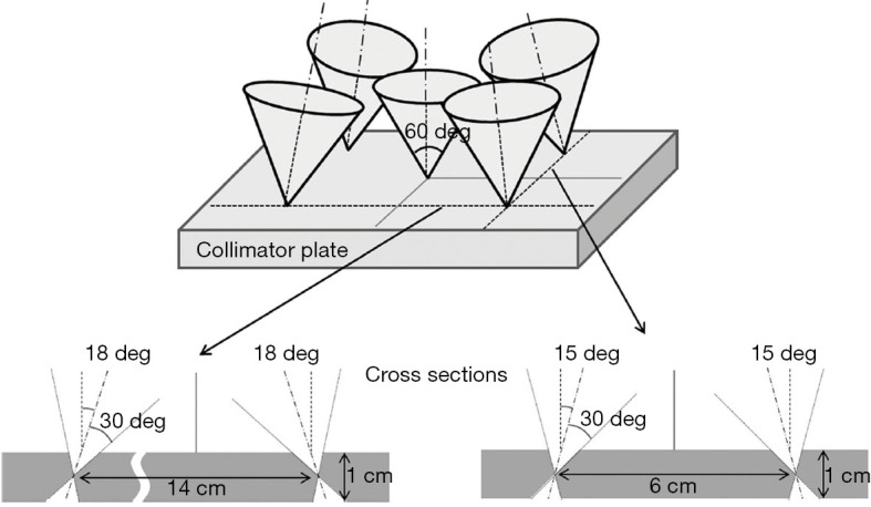
Single photon emission computed tomography (SPECT) is an important imaging modality for various applications in nuclear medicine. The use of multi-pinhole (MPH) collimators can provide superior resolution-sensitivity trade-off when imaging small field-of-view compared to conventional parallel-hole and fan-beam collimators. Besides the very successful application in small animal imaging, there has been a resurgence of the use of MPH collimators for clinical cardiac and brain studies, as well as other small field-of-view applications. This article reviews the basic principles of MPH collimators and introduces currently available and proposed clinical MPH SPECT systems.

Keywords: Single photon emission computed tomography (SPECT); brain; cardiac; collimator; multi-pinhole.


Conflict of interest statement

Conflicts of Interest: All authors have completed the ICMJE uniform disclosure form (available at http://dx.doi.org/10.21037/qims-19-1036). FJB reports personal fees and non-financial support from MILabs, grants from Dutch Foundation for Scientific Research (NWO), during the conduct of the study. In addition, FJB has patents on several pinhole imaging devices issued. He is founder, shareholder, and part time CEO of MILabs B.V, a company that develops pinhole PET and SPECT systems like the U-SPECT and G-SPECT-I scanners that were addressed in the present paper. GSPM reports that she has a patent “Optimized Multi-Pinhole Collimator for Dual-Purpose Clinical and Preclinical Imaging” (US 9,431,140 B2) issued. In addition, GSPM serves as an unpaid editorial board member of Quantitative Imaging in Medicine and Surgery. The other authors have no conflicts of interest to declare.

Figures

Figure 1
Figure 1
Schematic sketch of NFRCDC, FOCDC, and FRCDC knife-edge pinhole designs [courtesy of Bal et al. (42)].
Figure 2
Figure 2
Pinhole imaging parameters. Dashed lines inside the detector and the pinhole plate show their central plane, respectively. The yellow star represents the origin of the gamma ray.
Figure 3
Figure 3
Schematic sketch of keel-edge (top) and knife-edge (bottom) pinhole designs.
Figure 4
Figure 4
Dual stage collimation with circular pinholes and an outer lead shield with square holes. With permission of MILabs B.V. Utrecht, The Netherlands.
Figure 5
Figure 5
Rectangular pinholes with rectangular FOV. (A) Semitransparent design drawing of a rectangular pinhole insert, showing the double-pyramid-shaped inside walls, which open up above and below the plane of the small square aperture. (B) Photograph of one of the many identical platinum–iridium inserts. (C) Top view showing the 0.3-mm square-pinhole aperture, located 2 mm below the opening on the top, and 5 mm above the large opening on the bottom [courtesy of Moore et al. (55)].
Figure 6
Figure 6
Simplified illustration of projection images generated using a spherical phantom. The ratio of utilized area to total area of detector is ~52% and ~79% for (A) single pinhole and (B) six-pinhole collimators with no multiplexing, respectively. For (C), there is ~93% usage with ~33% multiplexing and no truncation. In (D), there is 100% usage with ~38% multiplexing and truncation. For (E), lofthole, dual stage collimation and rectangular pinhole, there is 100% usage with no multiplexing, while truncation may or may not be present depending on the magnification of the spherical phantom.
Figure 7
Figure 7
Experimental projections and axial SPECT images from the Defrise phantom imaged under different pinhole configurations [courtesy of Mok et al. (36)].
Figure 8
Figure 8
Monte Carlo simulations of a digital mouse phantom with different numbers of pinholes. Significant artifacts occur in the regular 4-pinhole pattern with multiplexing (yellow arrows) while they are not seen as significantly in the 5-pinhole pattern with a higher degree of multiplexing.
Figure 9
Figure 9
Parallax or DOI effect due to gamma-rays entering the detector at oblique angles. Photons being detected with a larger incident angle would be more blurred out (red point spread function) compared to those with a smaller incident angle (blue point spread function).
Figure 10
Figure 10
Seven-pinhole array. Left: close-up view of the collimator at the entrance. Right: the exit surface that has shielding to prevent projection overlapping [courtesy of Vogel et al. (33)].
Figure 11
Figure 11
Left: experimental setup of the 9-pinhole MPI SPECT system with a torso phantom. Right: non-multiplexed projection data of the phantom with cardiac and liver uptakes [courtesy of Funk et al. (64)].
Figure 12
Figure 12
Left: Discovery NM 530c featuring a gantry that is similar to a conventional cardiac SPECT camera, with a different detector assembly that allows completely stationary acquisition. Right: sample pinhole aperture from Discovery NM 530c (courtesy of Taipei General Veterans Hospital).
Figure 13
Figure 13
Left: LaPET scanner with a collimator insert. Right: Lofthole with a circular aperture and a rectangular exit window [courtesy of Van Audenhaege et al. (81)].
Figure 14
Figure 14
The UCSF 20-pinhole SPECT collimator (courtesy of Dr. Youngho Seo).
Figure 15
Figure 15
Side views of a combined MPH and fan-beam collimator system [courtesy of King et al. (7)].
Figure 16
Figure 16
Illustration of a G-SPECT-I scanner. (A) G-SPECT-I system with three optical cameras and a user interface for volume-of-interest (VOI) selection; (B) multi-pinhole collimator of G-SPECT-I system. All 54 pinholes distributed over three rings are focused on the complete data volume [CDV: the spherical object shown (A) in the FOV]. Each pinhole has an opening angle of 27°, resulting in a CDV with a transaxial diameter Rc of 100 mm and axial length L of 60 mm [courtesy of Chen et al. (82)]. (C) Comparison of resolution of G-SPECT-I equipped with a 38 cm collimator with a dual head Siemens Symbia system at equal scan time and equal dose based on physical experiments (with permission of MILabs B.V. Utrecht, The Netherlands).
Figure 17
Figure 17
A sample 9-pinhole collimator (MPGP) mounted on a clinical SPECT scanner.
Figure 18
Figure 18
The 12-pinhole collimator plate for cardiac imaging.
Figure 19
Figure 19
Proposed small organ MPH collimator [courtesy of Bae et al. (84)].
Figure 20
Figure 20
Left: (A) pod geometry. A planar cut through the central detector and two peripheral detectors from a seven-pinhole pod; (B) a planar cut through the central pod and one peripheral pod; (C) 3D rendering view of the 49-pinhole configuration. Right: representation of robotic SPECT imaging for a patient in position for radiation therapy. (A) Parallel-hole SPECT imaging of the head; (B) 49-pinhole SPECT imaging of the thorax; (C) robotic SPECT system retracted to allow normal external beam radiation therapy gantry motion [courtesy of Bowsher et al. (85)].
Figure 21
Figure 21
The compression process and scanner geometry for MBT. (A) Transparent plates compress the breast and a VOI is selected using optical cameras. (B) After the scan volume selection, the collimator plates and gamma detectors move into scanning position (arrows). (C) Collimator and gamma detector in scanning position, with insert showing collimator details. (D) Perpendicular cross-section through collimator-detector set-up showing the pinhole geometry. Dashed lines indicate the pinhole axes, which converge on a line 40 mm from the collimator. Arrows indicate the rotation of the whole scanner (including detectors, collimators and actuators) to enable acquisitions of different views [courtesy of van Roosmalen et al. (11)].
Figure 22
Figure 22
The 45 detector modules are arranged in 3 rows in the proposed dynamic MPH cardiac SPECT design [courtesy of Uzun Ozsahin et al. (87)].
Figure 23
Figure 23
The preliminary prototype design of AdaptiSPECT-C together with a cropped XCAT phantom positioned inside. This design consists of three hexagonal detector rings: caudal ring with 9 detectors, middle ring with 9 detectors, and quasi-vertex ring with 5 detectors. Shown are the 2 cm thick aperture plate with a single aperture per detector and the 23 hexagonal detectors (courtesy of Dr. Kesava S. Kalluri).
Figure 24
Figure 24
Five pinholes are located on a pinhole plate for the triple-head SPECT system. The thickness of the pinhole plate is 1 cm and each pinhole has a knife edge at the half depth of the pinhole plate. The axis of each pinhole has a different angle [courtesy of Ogawa et al. (94)].
Figure 25
Figure 25
GATE simulation setup using (A) ellipsoid detector and (B) flat detector, with point-sources located at 150 mm from the pinhole aperture [courtesy of Bhusal et al. (95)].
Figure 26
Figure 26
Proposed design of the integrated SPECT/MRI instrument (courtesy of Busca et al. (100)].

Similar articles

Cited by

References

    1. Beekman F, van der Have F. The pinhole: gateway to ultra-high-resolution three-dimensional radionuclide imaging. Eur J Nucl Med Mol Imaging 2007;34:151-61. 10.1007/s00259-006-0248-6 - DOI - PubMed
    1. Furenlid LR, Wilson DW, Chen YC, Kim H, Pietraski PJ, Crawford MJ, Barrett HH. FastSPECT II: a second-generation high-resolution dynamic SPECT imager. IEEE Trans Nucl Sci 2004;51:631-5. 10.1109/TNS.2004.830975 - DOI - PMC - PubMed
    1. Bowen JD, Huang Q, Ellin JR, Lee TC, Shrestha U, Gullberg GT, Seo Y. Design and performance evaluation of a 20-aperture multipinhole collimator for myocardial perfusion imaging applications. Phys Med Biol 2013;58:7209-26. 10.1088/0031-9155/58/20/7209 - DOI - PMC - PubMed
    1. Bocher M, Blevis IM, Tsukerman L, Shrem Y, Kovalski G, Volokh L. A fast cardiac gamma camera with dynamic SPECT capabilities: design, system validation and future potential. Eur J Nucl Med Mol Imaging 2010;37:1887-902. 10.1007/s00259-010-1488-z - DOI - PMC - PubMed
    1. Lee TC, Ellin JR, Huang Q, Shrestha U, Gullberg GT, Seo Y. Multipinhole collimator with 20 apertures for a brain SPECT application. Med Phys 2014;41:112501. 10.1118/1.4897567 - DOI - PMC - PubMed