Review
. 2020 Sep;145(3):237-258.
doi: 10.1007/s11120-020-00782-3. Epub 2020 Oct 5.

A brief history of how microscopic studies led to the elucidation of the 3D architecture and macromolecular organization of higher plant thylakoids

Affiliations
Review

A brief history of how microscopic studies led to the elucidation of the 3D architecture and macromolecular organization of higher plant thylakoids

L Andrew Staehelin et al. Photosynth Res. 2020 Sep.

Abstract

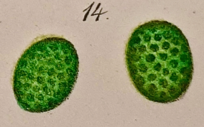
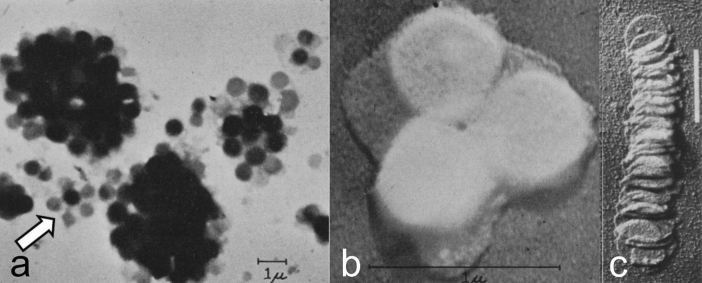
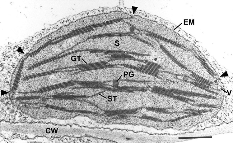
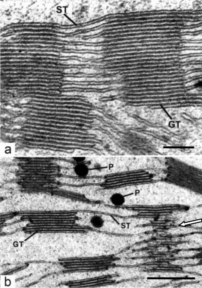
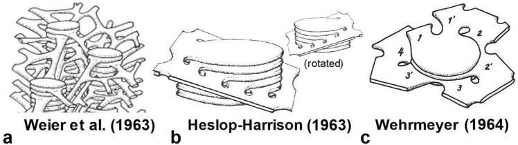
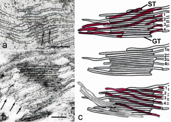
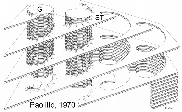
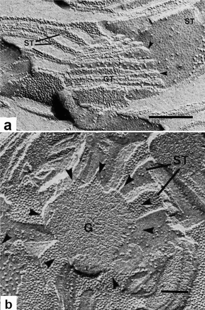
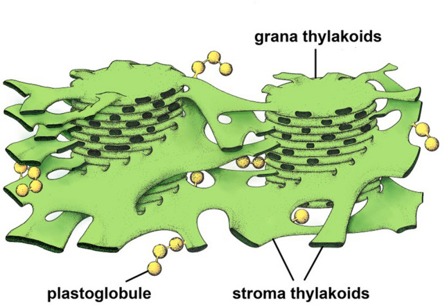
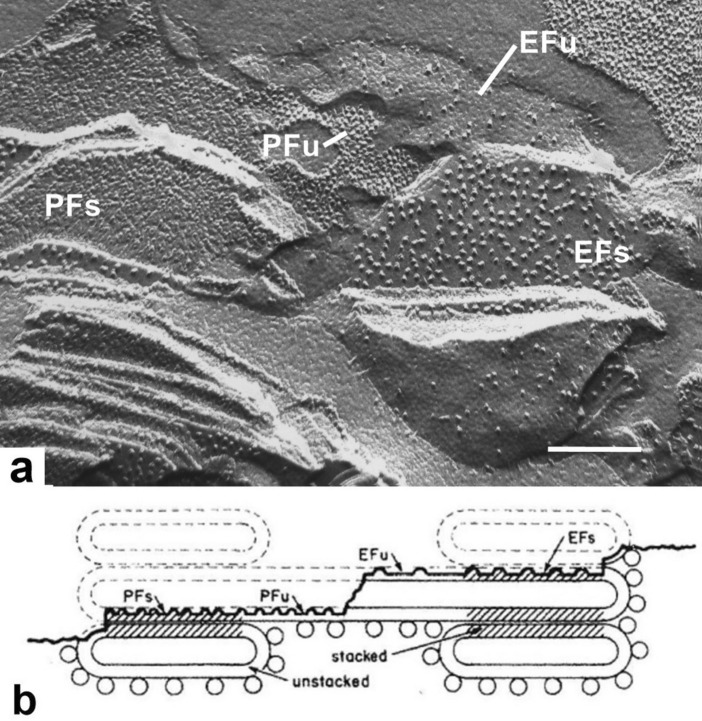
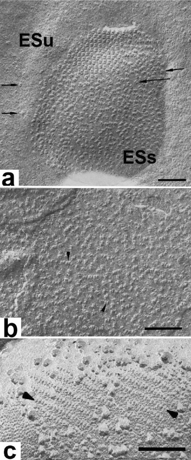
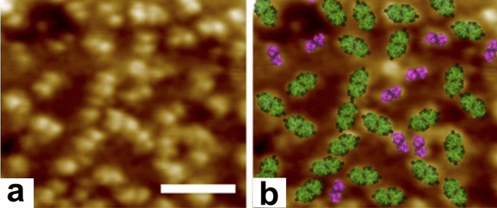
Microscopic studies of chloroplasts can be traced back to the year 1678 when Antonie van Leeuwenhoek reported to the Royal Society in London that he saw green globules in grass leaf cells with his single-lens microscope. Since then, microscopic studies have continued to contribute critical insights into the complex architecture of chloroplast membranes and how their structure relates to function. This review is organized into three chronological sections: During the classic light microscope period (1678-1940), the development of improved microscopes led to the identification of green grana, a colorless stroma, and a membrane envelope. More recent (1990-2020) chloroplast dynamic studies have benefited from laser confocal and 3D-structured illumination microscopy. The development of the transmission electron microscope (1940-2000) and thin sectioning techniques demonstrated that grana consist of stacks of closely appressed grana thylakoids interconnected by non-appressed stroma thylakoids. When the stroma thylakoids were shown to spiral around the grana stacks as multiple right-handed helices, it was confirmed that the membranes of a chloroplast are all interconnected. Freeze-fracture and freeze-etch methods verified the helical nature of the stroma thylakoids, while also providing precise information on how the electron transport chain and ATP synthase complexes are non-randomly distributed between grana and stroma membrane regions. The last section (2000-2020) focuses on the most recent discoveries made possible by atomic force microscopy of hydrated membranes, and electron tomography and cryo-electron tomography of cryofixed thylakoids. These investigations have provided novel insights into thylakoid architecture and plastoglobules (summarized in a new thylakoid model), while also producing molecular-scale views of grana and stroma thylakoids in which individual functional complexes can be identified.

Keywords: Atomic force microscopy; Chloroplasts; Electron microscopy; Electron tomography; Freeze-fracture electron microscopy; Thylakoid model.


Conflict of interest statement

No conflicts of interest and no outside funding.

Figures

Fig. 1
Fig. 1
Chloroplast drawings of Arthur Meyer (1883) that were hand-colored by publisher. The images highlight the chloroplast grana he observed in leaf cells of Acanthephippium
Fig. 2
Fig. 2
Early electron micrographs of isolated chloroplast membranes. a Clusters of grana from individual, disrupted spinach chloroplasts air-dried on grid. The arrow points to a small, separated cluster of grana that appear interconnected by membranes (from Granick and Porter 1947). b Cluster of three, round, gold-shadowed grana “stacks” at high magnification (from Granick and Porter 1947). c Disassembled and gold-shadowed, disrupted granum of the shade plant Aspidistra that resembles a toppled stack of coins. From Steinmann (1952). Bar 1.0 mm
Fig. 3
Fig. 3
Thin section electron micrograph of a chemically fixed chloroplast in a young tobacco leaf. The chloroplast lies flat against the plasma membrane and the cell wall (CW) and presents a more or less elliptical outline. The stacked grana thylakoids (GT) are interconnected by non-stacked stroma thylakoids (ST). Stroma (S) surrounds the membranes, and the lightly stained regions of the stroma indicates the presence of DNA. Because this chloroplast was still growing, when it was fixed for TEM analysis, the grana stacks vary in height and have irregular margins. A few plastoglobules (PG) lie adjacent to stroma thylakoids. Two envelope membranes (EM) form the boundary layer of the chloroplast. The arrowheads point to contact sites between thylakoid membranes and the inner envelope membrane. Such sites are frequently seen in growing chloroplasts and most likely represent sites of galactolipid transfer from the lipid-synthesizing inner envelope membrane to the growing thylakoid membranes. A small vesicle (V) is seen close to the inner envelope membrane. They are also seen infrequently. From Staehelin (1986); Bar 0.5 mm
Fig. 4
Fig. 4
Higher magnification micrographs of grana (GT) and stroma thylakoids (ST) in corn and spinach chloroplasts. a Corn chloroplast. In this cross-sectional view, the continuity between stacked grana thylakoids and non-stacked stroma thylakoids is clearly seen, as is the partial overlap between two grana. In many instances, the grana and stroma thylakoids appear to be connected to each other either through bifurcated stroma thylakoids or through membranes that continue in a planar manner between the two types of thylakoid. Configurations of this kind dominated early models of membrane architecture. The ratio of grana thylakoids to stroma thylakoids approximates 2:1. b Grana thylakoids and stroma thylakoids of a spinach chloroplast. The tangentially sectioned granum seen on the lower right side illustrates the angle (arrow) between the different planes of the grana and stroma membranes. The latter are also evenly spaced (cf. Fig. 7). Plastoglobuli (P). a From Paolillo and Falk (1966); b From Staehelin (1986). a, b Bars 0.5 mm
Fig. 5
Fig. 5
Early models of chloroplast membrane architecture. a The grana and stroma thylakoids of the Hodge et al. (1955) model are shown as connected through Y-shaped junctional regions. b The competing model of Steinman and Sjöstrand (1955) shows expansive stroma thylakoids and restricted grana thylakoids. Where the non-stacked stroma thylakoids enter the grana stack, they become grana thylakoids. c 3D chloroplast model of Eriksson et al. (1961) based on the premise that the thylakoids are arranged as in (b)
Fig. 6
Fig. 6
Three-dimensional chloroplasts models of the 1960s that replaced those proposed in the 1950s (Fig. 5). a The characteristic feature of the Weier et al. (1963) model is the much exaggerated tubularity of the stroma thylakoids. b The model shows a planar stroma thylakoid intercepting a cylindrical grana stack. The two images illustrate the front and back sides of the model and the series of connections that connect the stroma thylakoid with the grana thylakoids. In this model, the partial helices formed by the stroma thylakoid are of opposite handedness on the near vs. far sides of a granum. c In the Wehrmeyer (1964) model the stroma thylakoid is depicted as a right-handed helix that spirals around the granum, while also suggesting a mechanism for spiral growth
Fig. 7
Fig. 7
Tangential sections and tracings of serial sections through a grana stack. a The non-stacked stroma thylakoids are angled with respect to the stacked grana thylakoids and show evidence for a step-like ascent (arrows) corresponding to the frequency of the grana thylakoids. b Three evenly spaced stroma thylakoids marked by arrows appear angled to the plane of the stacked grana thylakoids in both the plane of the section and in the third dimension. c Tracings from three selected sections in a series of ten serial sections of a granum and associated stroma thylakoids from a bean chloroplast. The median section is reproduced in all three images, with the tangential sections from the near side (uppermost image) and far side (lowermost image) of the granum superimposed upon it. Stroma thylakoids in the tangential sections are shown in red. The helical structure of the stroma thylakoids can be inferred within a series of sections by comparing the tilt of the membranes as seen on the near versus the far tangents. Stroma thylakoids that could be followed completely around the grana stack are numbered (1–4). a, b From Paolillo and Falk (1966); c based on Figs. 1–10 in Paolillo and Reighard (1967); a, b Bars 0.1 mm
Fig. 8
Fig. 8
Three-dimensional model depicting how the grana thylakoids are connected to the stroma thylakoids. The stroma thylakoids (ST) are shown to be organized as parallel sheets that form right-handed helices around each granum (G). On the right side, two grana are omitted to illustrate eight thylakoids that spiral around the grana stacks. At the left, seven of the eight stroma thylakoids were omitted so that the numerous connections between grana and stroma lamellae could be drawn in. From Paolillo (1970)
Fig. 9
Fig. 9
Freeze-fracture electron micrographs illustrating the 3D relationship between stroma thylakoids and their associated grana thylakoids. a The grana thylakoids (GT) in the center are fractured obliquely, while the stroma thylakoid (ST) on the right is seen in a face-on view. Two of the junctional connections between the grana and the stroma thylakoids are marked by arrowheads. On the left side, several parallel stroma thylakoids are cross-fractured. All of the structural features of the membranes seen in this micrograph are consistent with multiple helical stroma thylakoids wound around the granum as postulated by the helical model. b Face-on view of a grana (G) stack with angled stroma thylakoids (ST) connected to its margins (arrowheads) and arranged like the blades of a conventional windmill with the central granum corresponding to the hub. The image also supports the helical model. a, b From Staehelin and van der Staay (1996). a, b Bars 0.2 mm
Fig. 10
Fig. 10
Etioplast of a chemically fixed pea cell with a large, well-organized prolamellar body (PLB), typical of seedlings kept for prolonged periods of time in darkness prior to exposure to light. Thylakoids (T) are attached to the margins of the PLB. From Staehelin (1986). Bar 0.3 mm
Fig. 11
Fig. 11
Electron tomography-based model of a grana stack and associated stroma thylakoids (ST) of an Arabidopsis chloroplast. a The grana thylakoids are colored yellow, and the stroma thylakoids are colored differently and numbered to allow for tracking their position in different views of the model (not shown). b Electron tomography model of two grana stacks (G, yellow) and a green colored stroma thylakoid that forms both a link between the two stacks and illustrates how stroma thylakoids spiral around and interact with grana stacks. The black arrowheads point to the typical, smaller size grana-stroma junctions that the helical stroma thylakoid forms with each grana thylakoid. The white arrowheads mark a stroma-grana membrane junction with double the width of the regular ones. Such large junctional slits arise when two junctions are formed adjacent to each other on a single grana thylakoid. a, b From Austin and Staehelin (2011) Copyright American Society of Plant Biologists
Fig. 12
Fig. 12
Electron tomography slice image of a lettuce chloroplast illustrating stacked grana thylakoids and non-stacked stroma thylakoids. Superimposed in the lower part of the micrograph is a 3D tomographic model that illustrates how two sub-groups of stroma thylakoids (blue, purple) bridge the space between two grana stacks (yellow). Thus, while the stroma thylakoids that form connections to the grana thylakoids are organized as right-handed helices (blue), those that connect the two sets of stroma thylakoids around the grana stacks are linked to each other through left-handed helices (purple). From Bussi et al. (2019). Bar 0.2 mm
Fig. 13
Fig. 13
Tomographic model depicting two clusters of plastoglobules (pg) that are closely associated with thylakoid membranes in an Arabidopsis chloroplast. How the plastoglobules are connected to thylakoid membranes and to each other is depicted in greater detail in the diagram Fig. 14. Grana thylakoids (gt) and stroma thylakoids (st). From Austin et al. (2006). Copyright American Society of Plant Biologists
Fig. 14
Fig. 14
3D model of thylakoid membranes with bound plastoglobules based on electron tomography reconstructions of cryofixed and plastic-embedded chloroplasts. The stroma thylakoids that spiral around the grana stacks form right-handed helices as postulated by the helical model. While some of the grana-connecting stroma thylakoids form right-handed helices, some fork to create left-handed helices. The plastoglobules are surrounded by and linked to each other and to the thylakoid membranes via a lipid monolayer that is continuous with the stroma leaflet of the thylakoid membrane bilayer
Fig. 15
Fig. 15
Freeze-fracture electron micrograph of spinach thylakoids. a The semi-circular structures on the left and the right correspond to fracture face views (labeled EFs and PFs) of grana thylakoids generated by splitting of the membrane bilayers as explained in (b). The fracture faces labeled EFu and Pfu belong to unstacked stroma thylakoids that connect the two adjacent grana stacks. The large EFs particles correspond to PSII-LHCII complexes, and the smaller EFu particles to incomplete PSII complexes. The PFs particles correspond to free LHCII and cytb6f complexes, whereas the PFu particles represent PSI, cytb6f, free LHCII and CF0 complexes. b Schematic diagram illustrating the nomenclature used to label freeze-fracture and freeze-etch images of thylakoid membranes (see a and Fig. 16a). From Staehelin and Arntzen (1983). a Bar 0.2 mm
Fig. 16
Fig. 16
a Luminal surface view of a spinach thylakoid exposed by freeze-etching. A central, dimeric particle-rich grana domain (ESs) is surrounded by a stroma thylakoid domain (ESu) with few dimeric particles (arrows). The dimeric particles represent the protruding parts of the oxygen-evolving complexes of the dimeric PSII/LHCII complexes. Some of the dimeric particles form a small lattice. b The dimeric particles (arrows) seen on the luminal surface of a grana membrane after removal of the oxygen-evolving proteins correspond to the core PSII/LHCII complexes, but are smaller than those seen in (a). c Stroma surface of an experimentally unstacked grana thylakoid with arrayed PSII particles (arrows). Together b and c demonstrate that the PSII complexes are integral membrane complexes that extend across the bilayer and protrude from both sides of the bilayer membranes. a From Staehelin (1976), b from Seibert et al. (1987), c from Miller (1976). a Bars 0.1 mm, b 0.1 mm, c 0.2 mm
Fig. 17
Fig. 17
Identification of PSII and cytb6f complexes on the luminal surface of grana thylakoids in an AFM micrograph. a The AFM topographic image displays the membrane extrinsic parts of PSII and cytb6f complexes on the luminal surface of a grana thylakoid. b Identification of the complexes seen in (a) based on affinity mapping of cytb6f (purple) and crystal structure fitting of PSII (green) and cytb6f. From Johnson et al. (2014), Copyright American Society of Plant Biologists. Bar 50 nm
Fig. 18
Fig. 18
Cryo-ET slice image of a grana membrane and an isosurface model of a dimeric PSII complex of spinach. a The dimeric particles (arrows) correspond to protruding parts of PSII/LHCII complexes. b Isosurface model (brown-gold) that shows the extrinsic subunits of the oxygen-evolving complexes of a dimeric PSII complex on the luminal membrane surface superimposed on a pseudo-atomic model of a PSII-LHCII super-complex. The position of the two additional spherical densities (white arrowheads) coincides with the position of the S-type LHCII trimers and probably respresents violaxanthin. From Kouril et al. (2011). a Bar 0.1 mm
Fig. 19
Fig. 19
In situ cryo-ET slice through a chloroplast of an intact Chlamydomonas cell. The micrograph illustrates the native molecular architecture of both grana and stroma thylakoid and chloroplast envelope membranes. The arrowheads point to ATP synthases (red), the luminal domain of a PSII complex (blue), and membrane-bound ribosomes (yellow). The margins of several converging thylakoids appear to be attached to a translucent layer associated with the stroma surface of the inner envelope membrane. From Wietrzynski et al. (2020). Bar 0.2 mm
Fig. 20
Fig. 20
Membranograms reconstructed from cryo-ET images of PSII-rich stacked grana (blue) and PSI-rich non-stacked stroma thylakoids (yellow) of Chlamydomonas. All membranograms illustrate densities located 2 nm above the membrane surface. The stroma-side membrane surfaces are labeled St, and the luminal-side surfaces are labeled Lu. A sharp grana-to-stroma membrane transition (arrowhead) is evident in all membranograms. The large, dimeric PSII complexes are limited to the grana membrane domains, whereas the smaller PSI particles are limited to stroma membranes. From Wietrzynski et al. (2020)

Similar articles

Cited by

References

    1. Adam Z, Charuvi D, Tsabari O, Knopf RR, Reich Z. Biogenesis of thylakoid networks in angiosperms: knowns and unknowns. Plant Mol Biol. 2011;76:221–234. - PubMed
    1. Anderson JM, Horton P, Kim EH, Chow WS. Towards elucidation of dynamic structural changes of plant thylakoid architecture. Phil Trans R Soc London. 2012;367:3515–3524. - PMC - PubMed
    1. Armond P, Staehelin LA, Arntzen CJ. Spatial relationship of photosystem-I, photosystem-II, and light harvesting complex in chloroplast membranes. J Cell Biol. 1977;73:400–418. - PMC - PubMed
    1. Austin JR, Staehelin LA. Three-dimensional architecture of grana and stroma thylakoids of higher plants as determined by electron tomography. Plant Physiol. 2011;155:1601–1611. - PMC - PubMed
    1. Austin JR, Frost E, Vidi P-A, Kessler F, Staehelin LA. Plastoglobules are lipoprotein subcompartments of the chloroplast that are permanently coupled to thylakoid membranes and contain biosynthetic enzymes. Plant Cell. 2006;16:1693–1703. - PMC - PubMed