. 2020 Jul:2020:3544-3548.
doi: 10.1109/EMBC44109.2020.9176474.

A microfluidic system integrated with shape memory alloy valves for a safe direct current delivery system

A microfluidic system integrated with shape memory alloy valves for a safe direct current delivery system

C Cheng et al. Annu Int Conf IEEE Eng Med Biol Soc. 2020 Jul.

Abstract

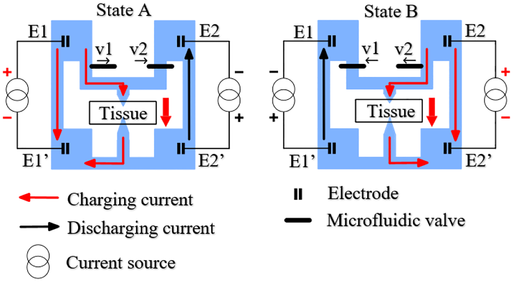
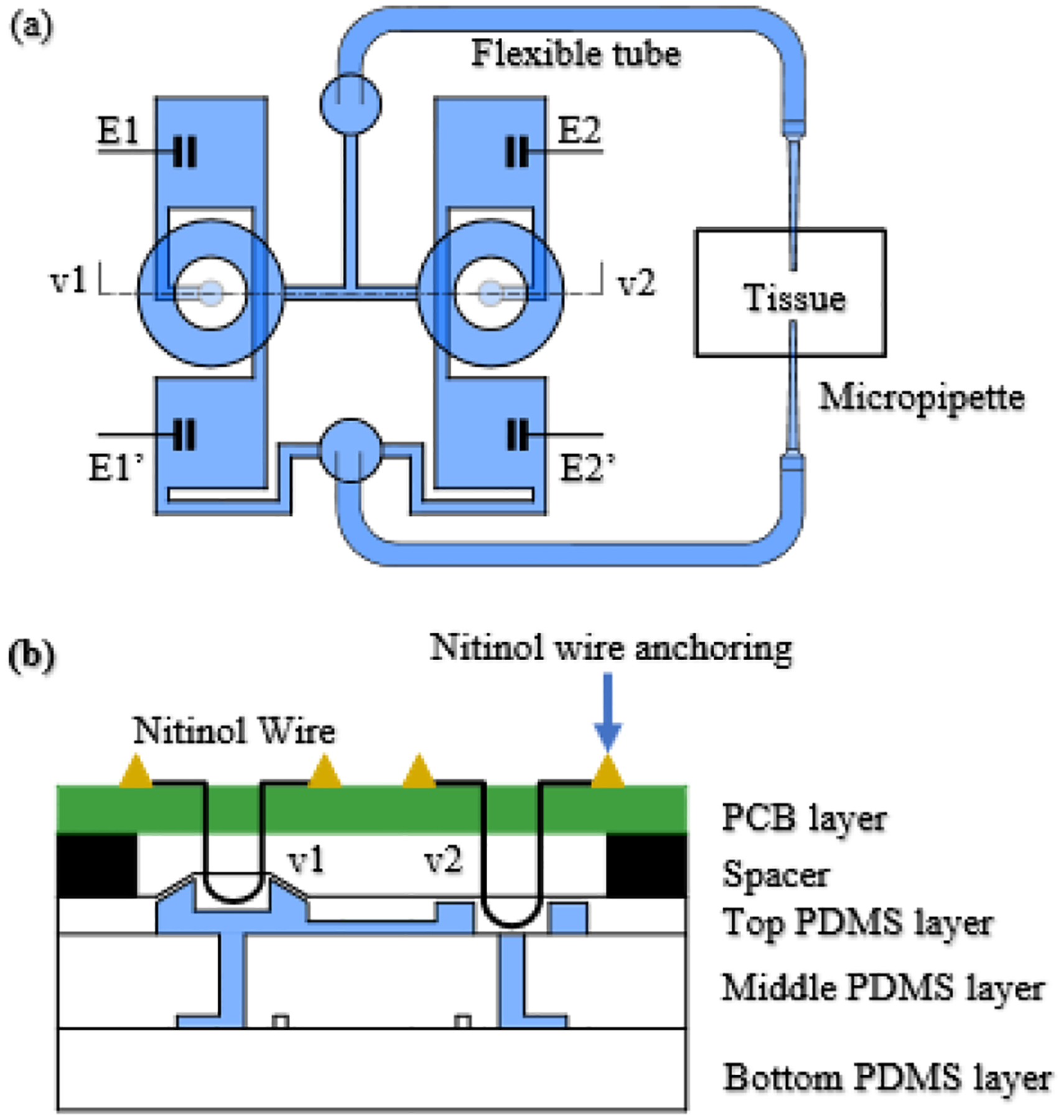
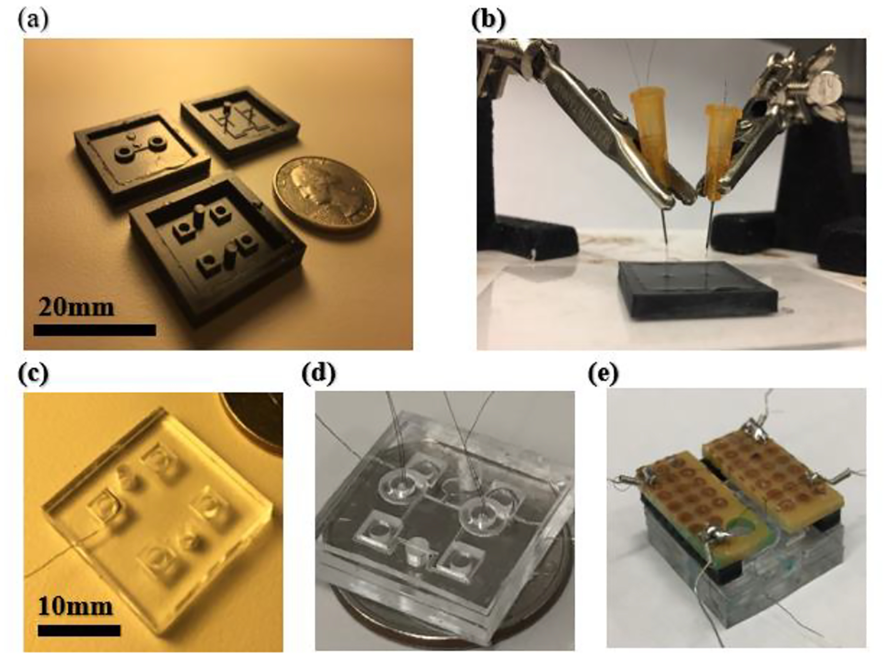
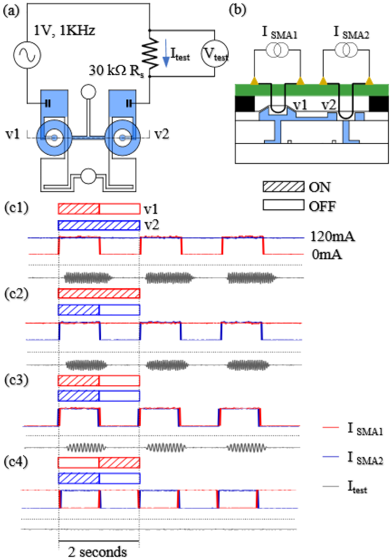
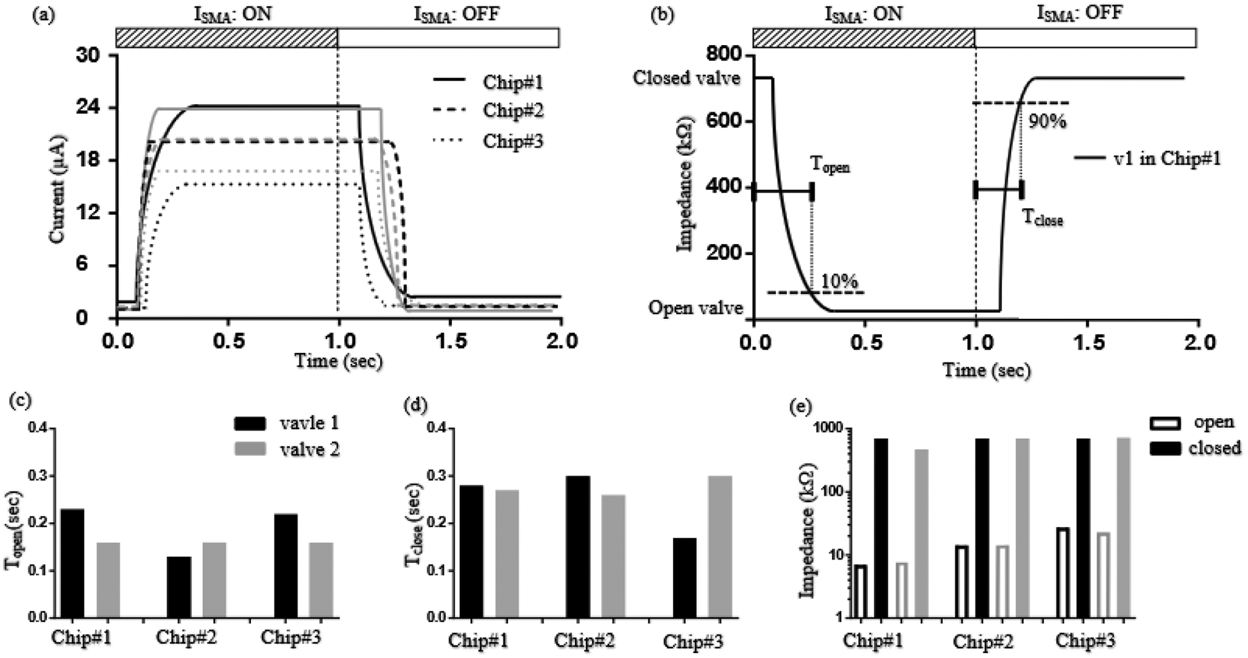
Direct current (DC) has potential as a clinical and scientific tool to accelerate wound healing, increase the permeability of the skin to drug treatment and modulate neural activity. But long duration delivery of DC unavoidably causes hazardous electrolysis at the tissue-electrode interface. To be able to deliver long duration DC, we previously proposed a design for a safe direct current stimulator (SDCS). This device uses alternating current that does not cause chemical reactions at the metal electrodes within the device, but delivers ionic direct current output to the tissue via microfluidic valves. We previously developed and published designs of multiple SDCS components including microfluidic, electronic, data processing, and energy systems. In this paper we focus on the development of the integrated microfluidics needed by the SDCS system. We developed a fabrication method and characterized valve performance within the multi-valve microfluidic system. We used poly-dimethylsiloxane (PDMS) to fabricate three microfluidic chips that integrated valves actuated by 50-µm Nitinol (NiTi) shape memory alloy (SMA) wire. We tested system operation by driving SMA valves with a current pulse and recording the valve response with an electrical assay. The valve operation complied with the SDCS system requirements. The time for valves to open was rapid at 0.177 ± 0.04 seconds, and the time for the valves to close was 0.265 ± 0.05 seconds. Open microfluidic channel impedance for unrestricted ionic current flow was 15.90 ± 8.28 kΩ and it increased by a factor of 40 to restrict ionic current flow at 678 ± 102 kΩ for the closed valves.


Figures

Figure 1.
Figure 1.
Two continually repeating states of the same SDCS device. To deliver a unidirectional current through the tissue, valves 1 (v1) and 2 (v2) open and close while two independent current sources deliver ionic current in sequential phases between electrodes E1 and E1’ and then between E2 and E2’ into channels filled with saline (blue).
Figure 2
Figure 2
Top and cross-section schematic views of SDCS with SMA valves. (a) Top view of the channel system and the leads to tissue. The device is filled with saline (blue). (b) Cross-section view showing the valve actuation mechanism. At valve 1 (v1), in response to driving current, the nitinol wire (black) shrinks and pulls the PDMS plunger (white) up to unblock the channel filled with saline (blue). Valve 2 (v2) is in resting state (not actuated).
Figure 3.
Figure 3.
Fabrication of the two-valve SDCS microfluidic chip. (a) 3D printed molds for top (upper-left), mid (upper-right) and bottom (bottom-left) PDMS layers. (b) Embedding nitinol wire on top PDMS layer. (c) A Pt coil electrode in a chamber within the bottom PDMS layer. (d) Bonded three-layer PDMS structure. (e) Final chip with transparency PDMS structure on bottom, black spacer in mid and brown PCB board on top.
Figure 4
Figure 4
Experimental set-up and current flow through the valves (Itest) in response to driving currents (ISMA1 and ISMA2). (a) Top-view diagram of a two-valve SDCS and electrical assay circuit. Blue sections are filled with 150mM saline. The white circles at the v1 and v2 structural centers are the plungers. (b) Cross-sectional diagram of the chip and the driving current circuits. (c1–c4) Itest in response to ISMA1 and ISMA2. Itest corresponds to the change of the electrical impedance through the microfluidic valves, v1 (red) and v2 (blue). Cross-hatches represent presence of the driving current of valve.
Figure 5
Figure 5
Electrical actuation and characterization of three two-valve chips. (a) Changes of current flow Itest in response to valve opening and closing operation. Shading (black or grey) differentiates the operations of valve 1 and valve 2 on each chip. (b) Corresponding impedance through valves with valve 1 operating in Chip#1. “Topen” is the duration from the onset of the driving current until the channel impedance drops to 10% of the closed valve impedance. “Tclose” is the duration from the offset of the driving current until 90% of the closed valve impedance has been restored. (c-e) The Topen (c), Tclose (d), and open/closed valve impedances (e) of the three chips. Shading (black or grey) differentiates valve 1 and valve 2 on each chip.

Similar articles

References

    1. Thakral G, LaFontaine J, Najafi B, Talal TK, Kim P, and Lavery LA, “Electrical stimulation to accelerate wound healing,” Diabetic Foot and Ankle. 2013. - PMC - PubMed
    1. Kloth LC and Feedar JA, “Acceleration of wound healing with high voltage, monophasic, pulsed current,” Phys. Ther, 1988. - PubMed
    1. Kloth LC, “Electrical Stimulation Technologies for Wound Healing,” Adv. Wound Care, 2014. - PMC - PubMed
    1. Banga AK, Donnelly R, and Stinchcomb AL, “Transdermal drug delivery,” Therapeutic Delivery. 2013.
    1. Prausnitz MR, “The effects of electric current applied to skin: A review for transdermal drug delivery,” Advanced Drug Delivery Reviews. 1996.

Substances

LinkOut - more resources